Tire sensor unit

a technology for tire sensors and sensors, applied in the direction of near-field systems using receivers, instruments, transportation and packaging, etc., can solve the problems of laborious process that becomes necessary to adjust the tire weight balance, and achieve the effect of convenient installation of the tire sensor uni

Inactive Publication Date: 2005-03-31
HONDA MOTOR CO LTD
View PDF3 Cites 37 Cited by
  • Summary
  • Abstract
  • Description
  • Claims
  • Application Information

AI Technical Summary

Benefits of technology

[0008] Since the tire sensor unit according to the present invention comprises the non-contact type power receiving portion which generates direct-current power by energy transmitted from the non-contact type power supply portion provided in the car body, the tire sensor unit can dispense with a battery, and it becomes unnecessary to replace a battery. Also, since it is unnecessary to attach a battery to the tire, the problem of the tire weight balance can be solved. In addition, by providing the tire sensor unit on a sheet-like substrate, it becomes easy to install the tire sensor unit in the tire or in the rubber of the tire.

Problems solved by technology

However, if a large-size battery is attached to a tire, a laborious process becomes necessary to adjust the weight balance of the tire.

Method used


Image

  • Tire sensor unit
  • Tire sensor unit
  • Tire sensor unit

Examples


Embodiment Construction

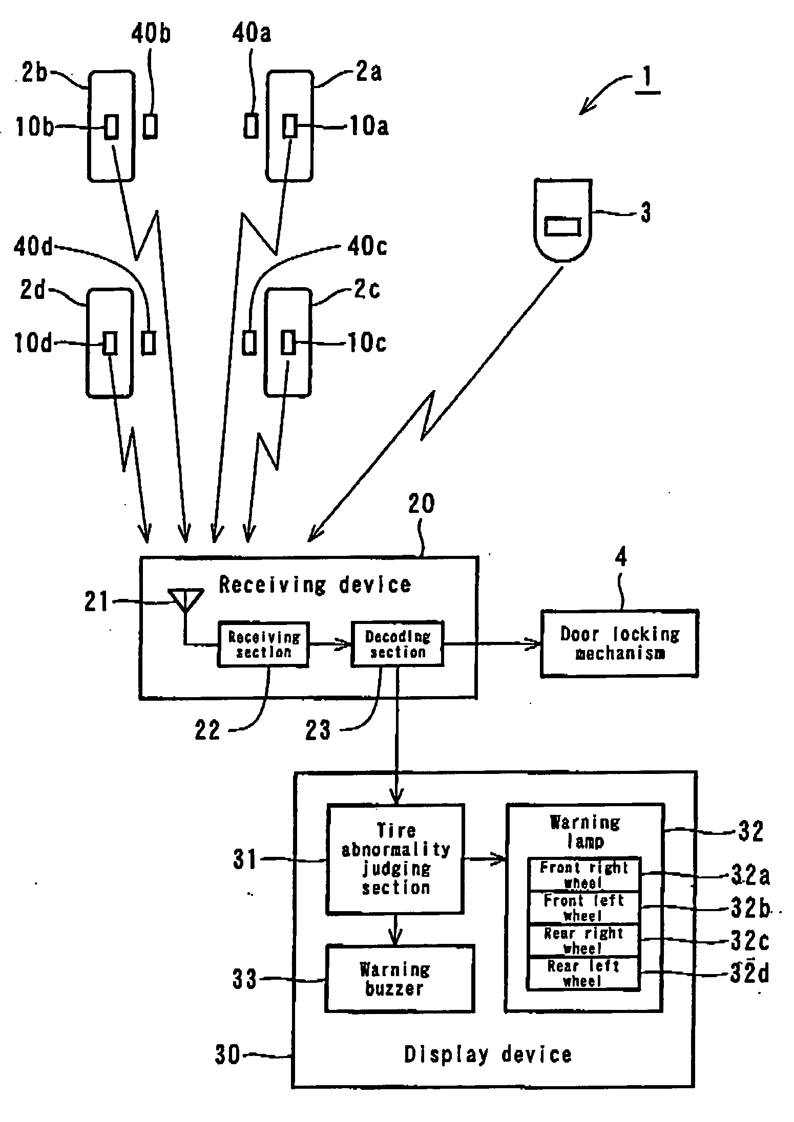
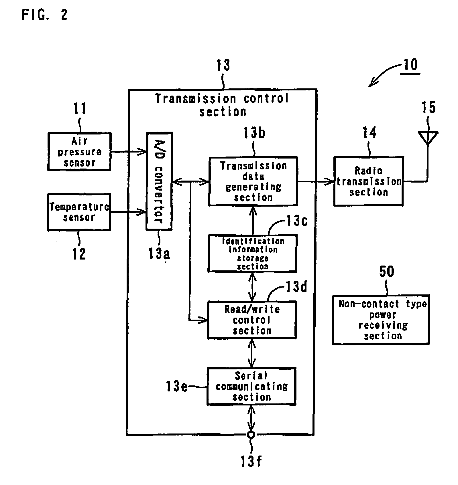
[0016] Hereinafter, embodiments of the present invention will be described with reference to the attached drawings. FIG. 1 is an overall block diagram of a tire monitoring system in which a tire sensor unit according to the present invention is employed, and FIG. 2 is a block diagram of the tire sensor unit according to the present invention.

[0017] As shown in FIG. 1, a tire monitoring system 1 is comprised of tire sensor units 10 (10a, 10b, 10c, and 10d), each being mounted on a respective tire 2 (a front right wheel 2a, a front left wheel 2b, a rear right wheel 2c, and a rear left wheel 2d) of a car, a receiving device 20 which is provided in the car body, a display device 30 which is provided in the car body, and non-contact type power supply portions 40 (40a, 40b, 40c, and 40d), each being provided in the car body and adjacent to the respective tire 2. The non-contact type power supply portion 40 is activated by electric power supplied from a battery of the car, and the non-con...


PUM


Abstract

According to the present invention, there is provided a tire sensor unit which receives electric power from a car body in a non-contact manner. The tire sensor unit 10 (10a-10d) is mounted on a corresponding tire 2 (2a-2d) of a car, and electric power is radio-transmitted from a corresponding non-contact type power supply portion 40 (40a-40d) provided in the car body to the tire sensor unit 10 by electromagnetic induction or by microwaves. The tire sensor unit 10 is provided with a non-contact type power receiving portion which generates direct-current power by energy transmitted from the non-contact type power supply portion 40 so as to supply electric power necessary for activating the tire sensor unit 10. The tire sensor unit 10 senses air pressure or the like, and radio-transmits the information to the receiving device 20.

Description

TECHNICAL FIELD [0001] This invention relates to a tire sensor unit which is mounted on each tire of a car, and more particularly a tire sensor unit which is driven by electric power fed from the car body in a non-contact manner, senses a tire condition such as tire pressure, and radio-transmits the information on the tire condition. BACKGROUND ART [0002] Japanese Unexamined Patent Publication No. H09-509488 discloses an active integrated circuit transponder and a sensor apparatus for sensing and transmitting car tire parameter data (tire pressure, tire temperature, number of tire rotations). Specifically, the active integrated circuit transponder with on-board power supply is mounted in a car tire, and a pressure sensor, a temperature sensor and a tire rotation sensor are mounted on a substrate along with the integrated circuit transponder chip, the power supply and an antenna. Upon receiving an interrogation signal from a remote source, the transponder transmits an encoded radio f...

Claims


Application Information

Patent Timeline
Patent Type & Authority Applications(United States)
IPC IPC(8): B60C23/02G01D7/00B60C23/04G08C17/02H04B5/00H04B5/02
CPCB60C23/0408B60C23/041H04B5/0062H04B5/0043H04B5/00
Inventor ICHINOSE, HIDEMIKONO, YASUHIRO
Owner HONDA MOTOR CO LTD
Why Eureka
Try Eureka