Lamp unit for forming a cut-off line and vehicular headlamp using the same

Active Publication Date: 2005-03-31
KOITO MFG CO LTD
View PDF7 Cites 33 Cited by
  • Summary
  • Abstract
  • Description
  • Claims
  • Application Information

AI Technical Summary

Benefits of technology

[0010] In view of this situation, an object of the present invention is to provide a compact or downsized lamp unit of a veh

Problems solved by technology

However, in the case of the vehicular lamp disclosed in Patent Document 2, the lamp configuration becomes

Method used


Image

  • Lamp unit for forming a cut-off line and vehicular headlamp using the same
  • Lamp unit for forming a cut-off line and vehicular headlamp using the same
  • Lamp unit for forming a cut-off line and vehicular headlamp using the same

Examples


Embodiment Construction

[0043] Hereinafter, an embodiment of the present invention will be described with reference to the drawings.

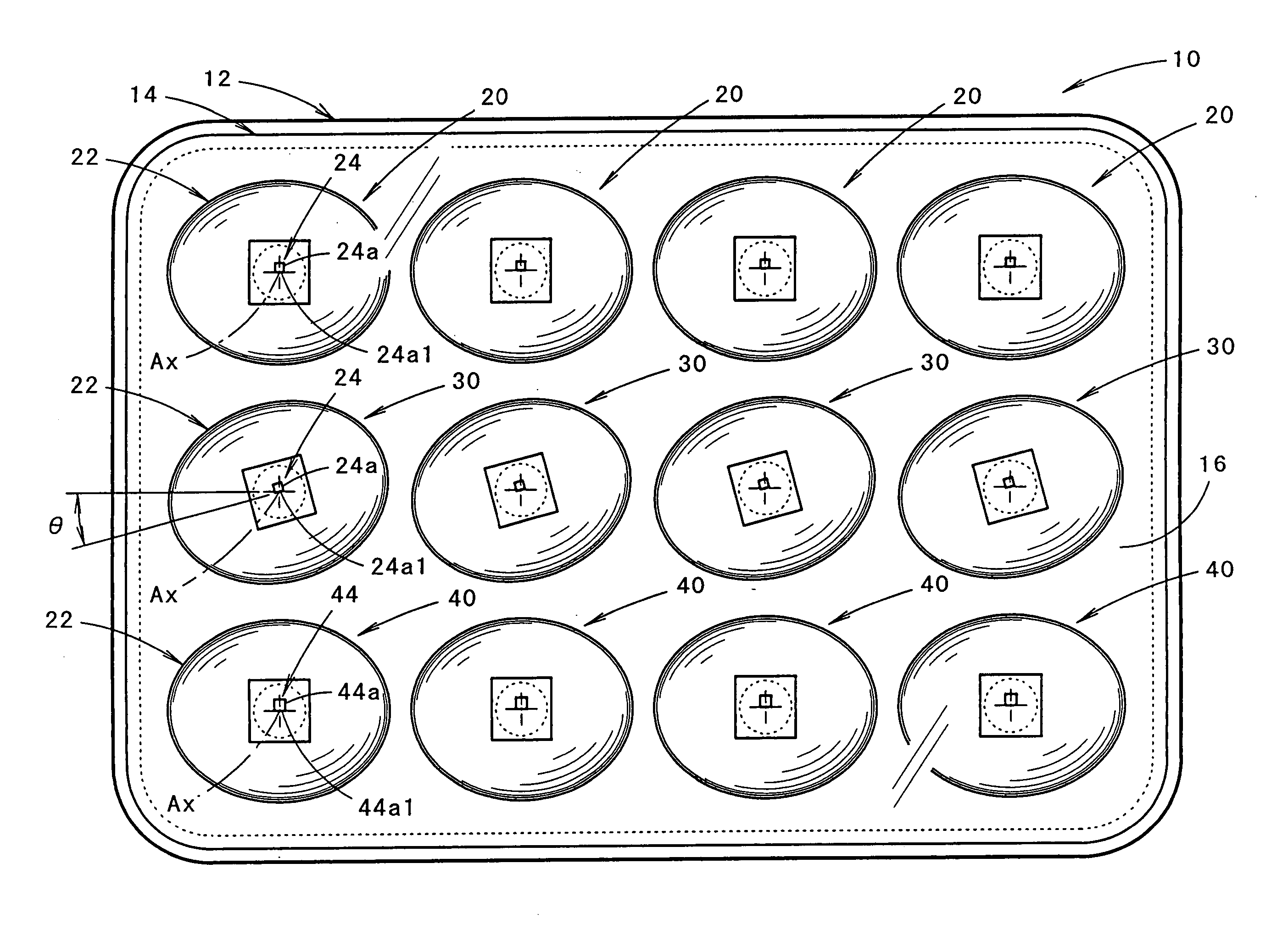
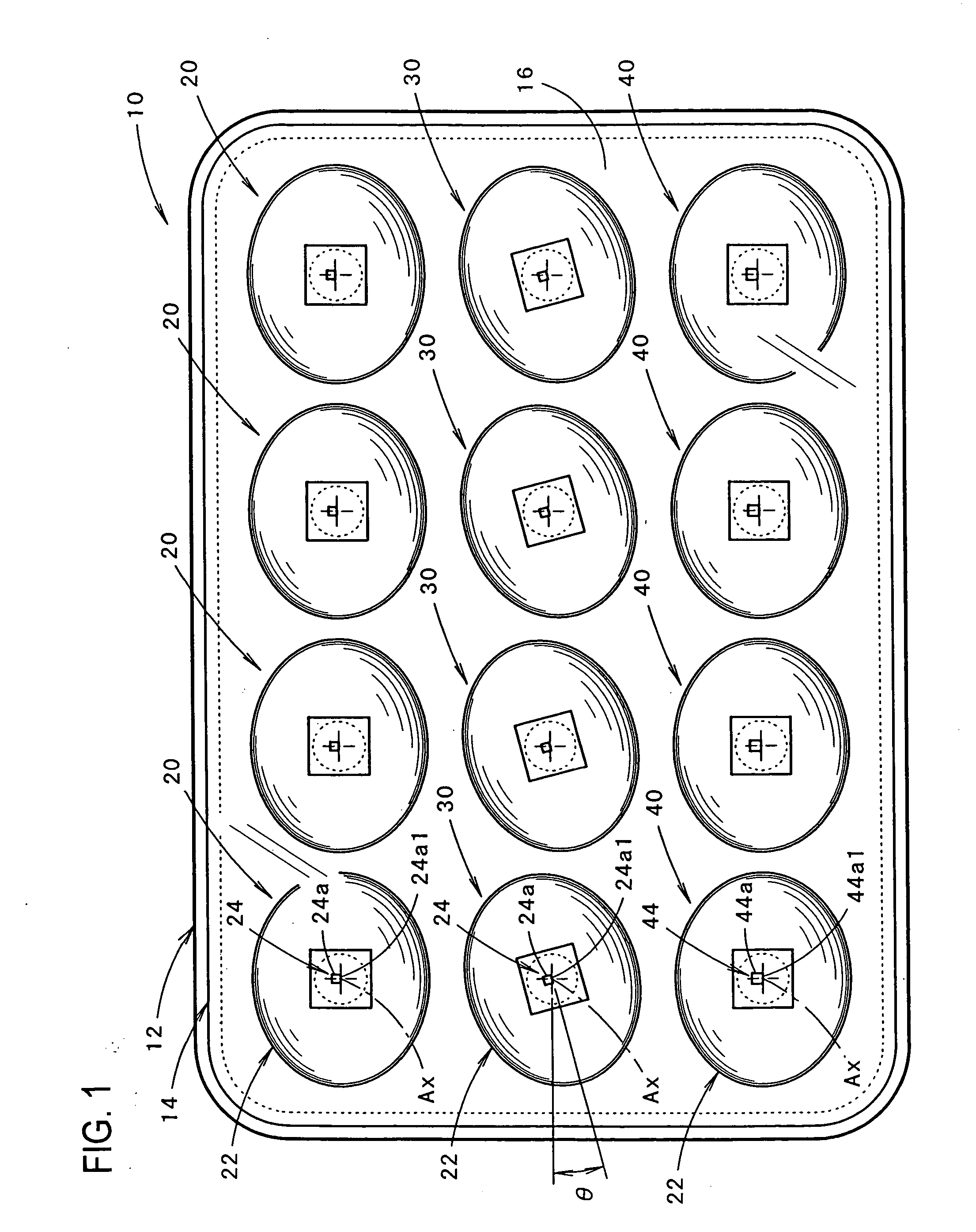
[0044]FIG. 1 is a front view showing a vehicular headlamp according to an embodiment of the present invention. As shown in the figure, a vehicular headlamp 10 is configured to accommodate 12 lamp units 20, 30, and 40 in three rows within a lamp chamber formed by a lamp body 12 and a translucent cover 14 attached to a front opening of the lamp body. Further, an inner panel 16 is provided in the lamp chamber so as to surround each of the lamp units 20, 30, and 40. In this embodiment, each of the four lamp units 20 disposed on the top row is the same in a configuration. Each of the four lamp units 30 disposed on the middle row and each of the four lamp units 40 disposed on the bottom row are the same in a configuration as well.

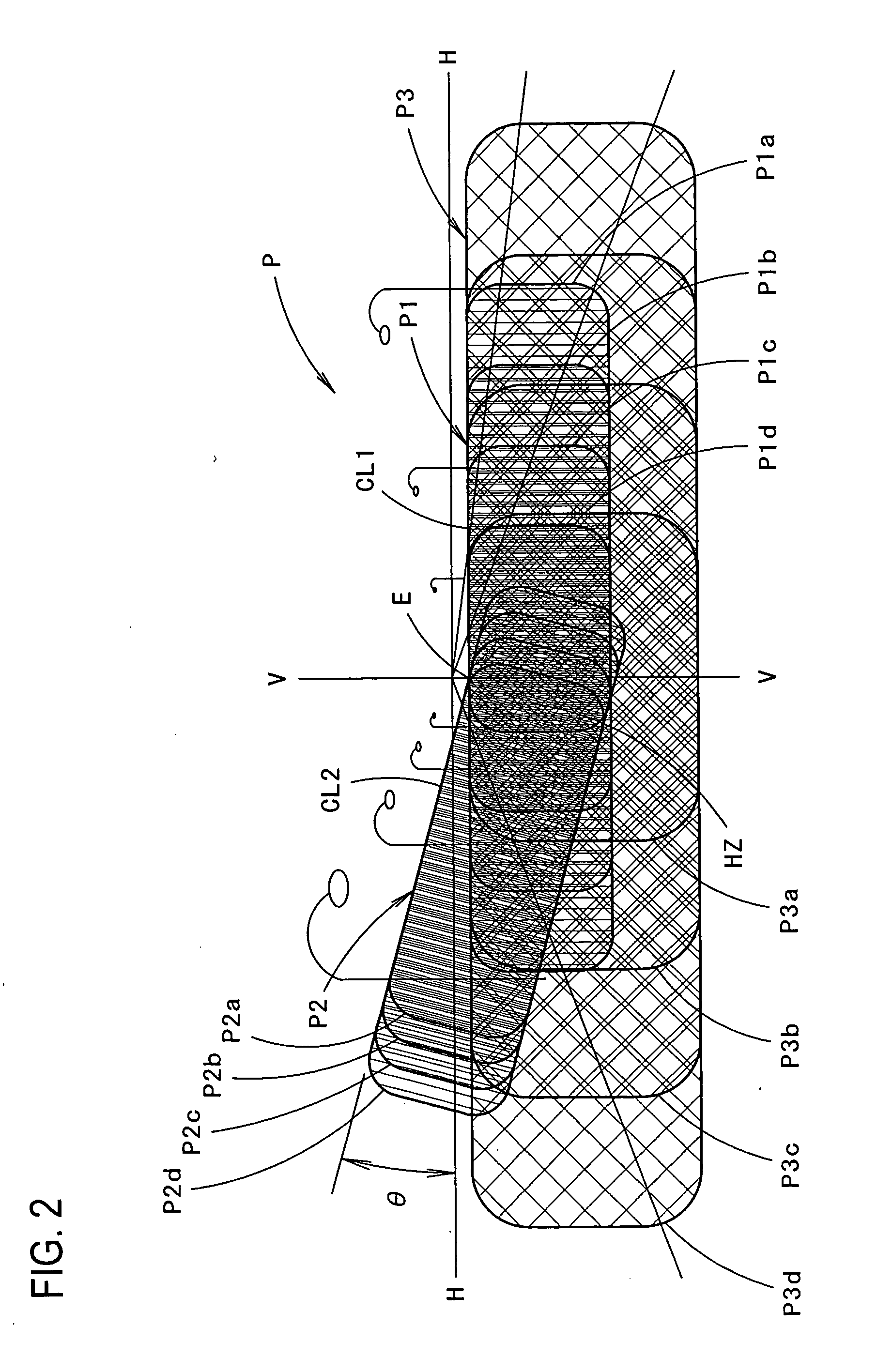
[0045]FIG. 2 is a perspective view showing the geometry of a light distribution pattern P formed by light radiated forward from the vehicular headlamp 10...


PUM


Abstract

A lamp unit for a vehicular headlamp includes a projection lens disposed on an optical axis extending in a vehicle longitudinal direction and a semiconductor light-emitting element having a light-emitting chip with a lower end edge formed linearly. The semiconductor light-emitting element is disposed in the rear of the projection lens facing forward so as to position the lower end edge 24a1 on the optical axis. The projection lens projects light from a point on the optical axis of the lower end edge within a vertical cross section as parallel light, and projects light from a point on the optical axis of the lower end edge within a horizontal cross section as diffused light.

Description

BACKGROUND OF INVENTION [0001] 1. Field of the Invention [0002] The present invention relates to a lamp unit of a vehicular headlamp used for forming a cut-off line. [0003] 2. Background Art [0004] It is conventionally known that a vehicular headlamp, as disclosed in, for example, Patent Document 1, is configured to form the geometry of a light distribution pattern with a cut-off line on an upper area based on light radiated from a plurality of lamp units. [0005] In addition, a vehicular lamp disclosed in Patent Document 2 is configured to reflect light radiated from a plurality of semiconductor light-emitting elements aligned in a horizontal direction toward the front of the lamp by a reflector. [0006] Patent Document 1: Japanese Patent Laid-Open Publication No. 2001-270383 [0007] Patent Document 2: Japanese Patent Laid-Open Publication No. 2003-31007 [0008] Assuming that the vehicular lamp disclosed in Patent Document 2 is used for a vehicular headlamp, it may be possible to form ...

Claims


Application Information

Patent Timeline
IPC IPC(8): F21S8/10F21S8/12F21V5/00F21W101/10F21Y101/02
CPCF21S48/1154F21S48/1163F21S48/1291H01L33/54F21V5/04F21Y2101/02F21S48/1747F21Y2115/10F21S41/143F21S41/155F21S41/27F21S41/663F21S41/153
Inventor ISHIDA, HIROYUKI
Owner KOITO MFG CO LTD
Why Eureka
Try Eureka