
Modular reactor containment system

a containment system and module technology, applied in the field of nuclear reactors, can solve the problems of primary system leakage not being able to uncover the core, complex construction of containment vessel and support pad for containment vessel,

Inactive Publication Date: 2005-03-31
GENERAL ELECTRIC CO
View PDF18 Cites 12 Cited by
  • Summary
  • Abstract
  • Description
  • Claims
  • Application Information

AI Technical Summary

Problems solved by technology

Construction of the containment vessel and the support pad for the containment vessel is a complex event requiring significant time and resources at the reactor site.
When a close fitting steel containment is combined with a passive closed loop isolation condenser and a natural circulating reactor system that contains a large water inventory, primary system leaks cannot uncover the core.

Method used


Image

  • Modular reactor containment system
  • Modular reactor containment system
  • Modular reactor containment system

Examples


Embodiment Construction

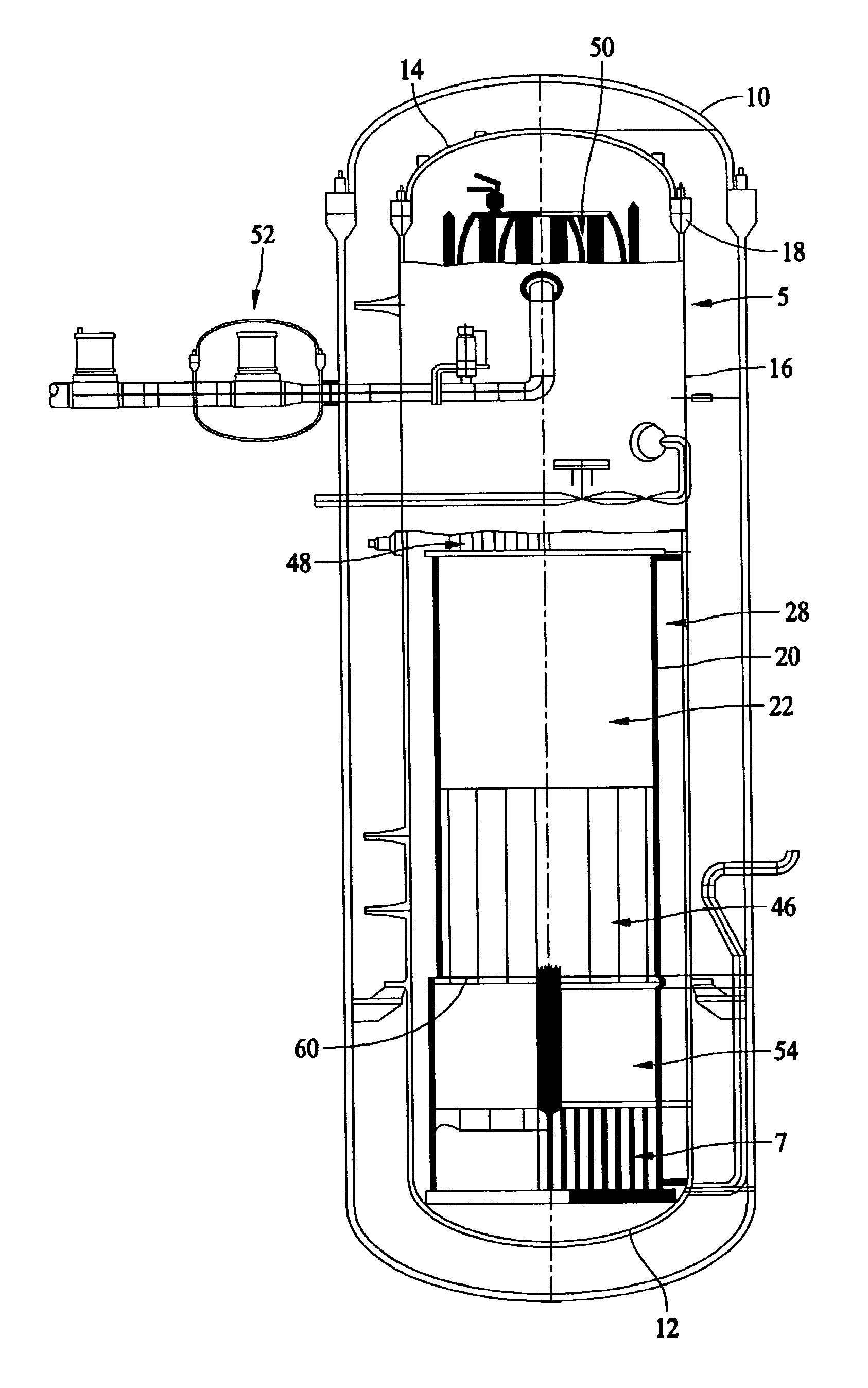
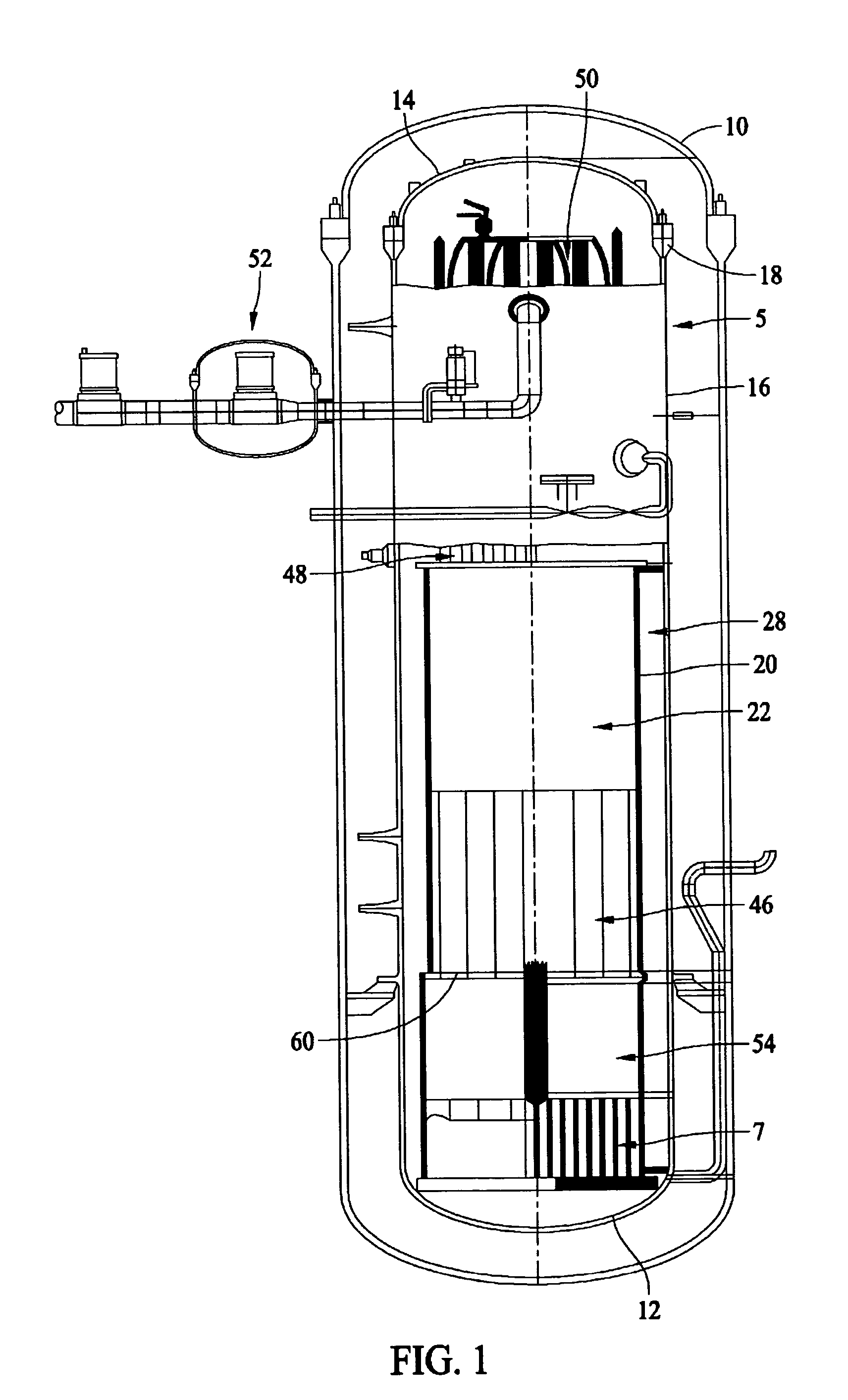
[0016] A boiling water nuclear reactor with a compact metal containment vessel in accordance with an exemplary embodiment of the present invention is described below in more detail. The compact containment vessel is smaller than known containment vessels and can be shop fabricated off-site for quick installation on-site. The high pressure compact steel containment vessel is used instead of the known relatively large and expensive concrete or steel containment vessels having a large suppression pool of water that are designed with relatively low pressure ratings. The compact containment vessel has a relatively high pressure rating.

[0017] The boiling water reactor with compact, dry containment vessel also employs a simple safety system which isolates and retains coolant inventory following a loss-of coolant accident (LOCA). The safety system is capable of maintaining core cooling and decay heat transfer using isolation condensers and equalizing lines without requiring coolant make-up...


PUM


Abstract

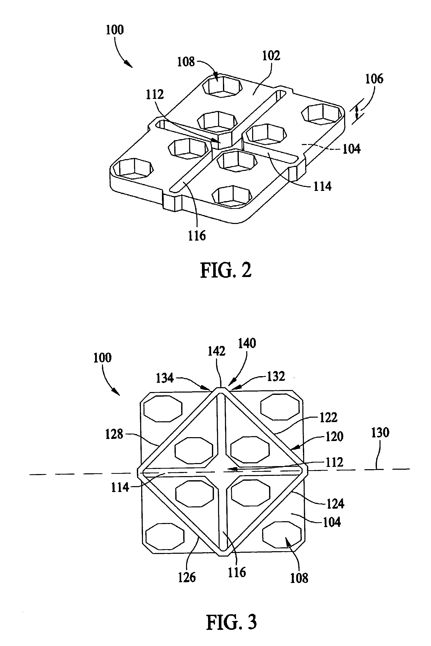
An apparatus for supporting fuel assemblies in a reactor pressure vessel including a core includes a plurality of support beams and at least one removable support plate disposed on at least one of the plurality of support beams.

Description

BACKGROUND OF THE INVENTION [0001] This invention relates generally to nuclear reactors, and more particularly, to removable components in nuclear boiling water reactors. [0002] One known boiling water reactor (BWR) includes a reactor pressure vessel (RPV) positioned in a containment building or vessel, and a containment cooling system (CCS). A typical containment vessel includes both a drywell and an enclosed wetwell disposed in the containment vessel. The wetwell provides an additional source of cooling water for the reactor in the event of a pipe rupture or loss of coolant accident (LOCA). The CCS includes a passive containment cooling system (PCCS) having a heat exchanger submerged in a cooling pool located outside the containment vessel. [0003] In the event of a LOCA, high-pressure fluid or steam is released from the RPV into the containment vessel. The steam is retained in the containment vessel, flows to the PCCS and is condensed in the PCCS heat exchanger. The steam condensa...

Claims


Application Information

Patent Timeline
Patent Type & Authority Applications(United States)
IPC IPC(8): G21C5/06G21C1/04
CPCG21C5/10Y02E30/40G21C13/024Y02E30/30
Inventor BOARDMAN, CHARLES EDWARDGALTMAN, JIMMY FRANKMOKLER, RONALD D.
Owner GENERAL ELECTRIC CO
Learn More