

Liquid delivering device
- Summary
- Abstract
- Description
- Claims
- Application Information
AI Technical Summary
Benefits of technology
Problems solved by technology
Method used
Image

Examples
first embodiment
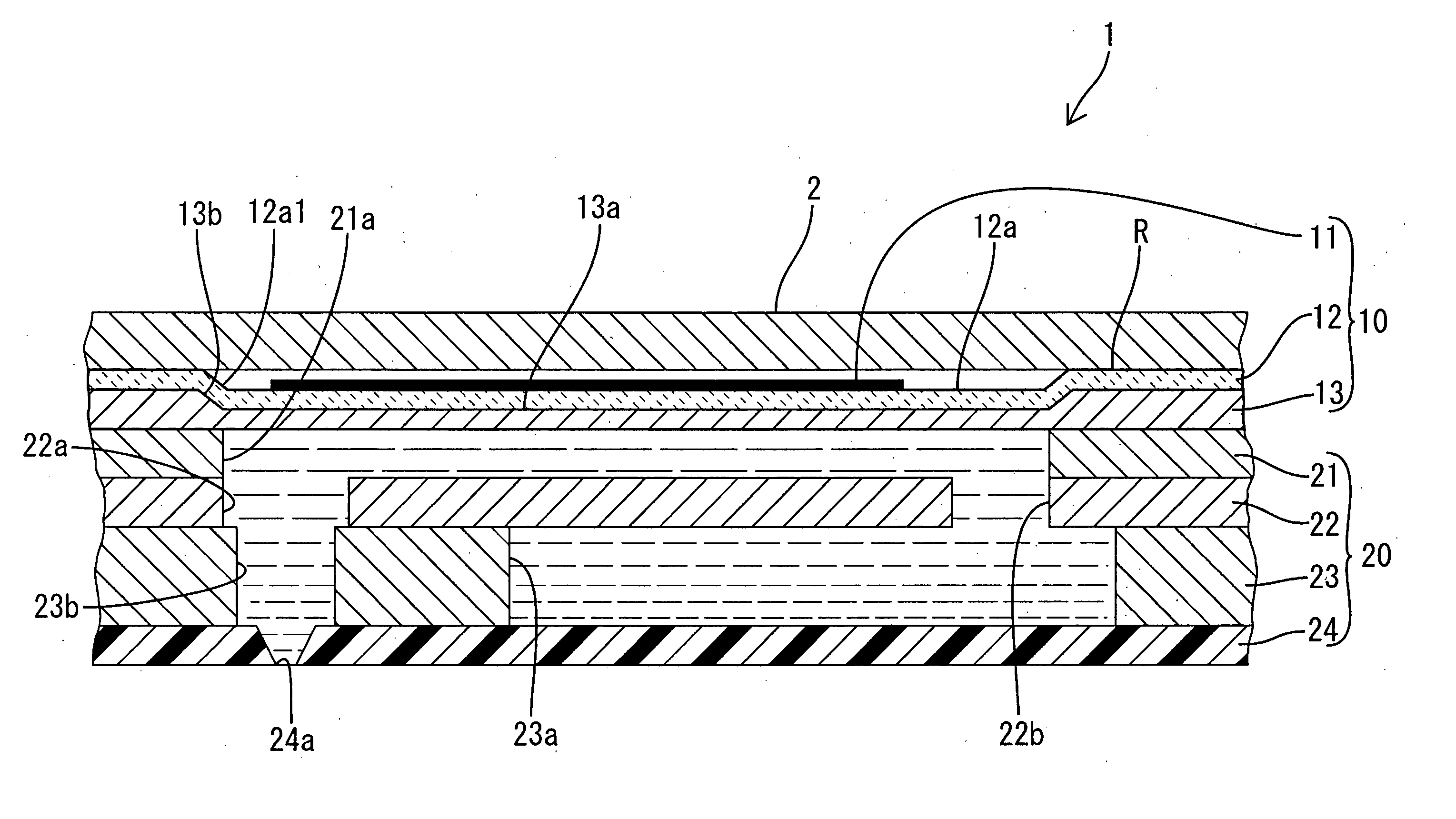
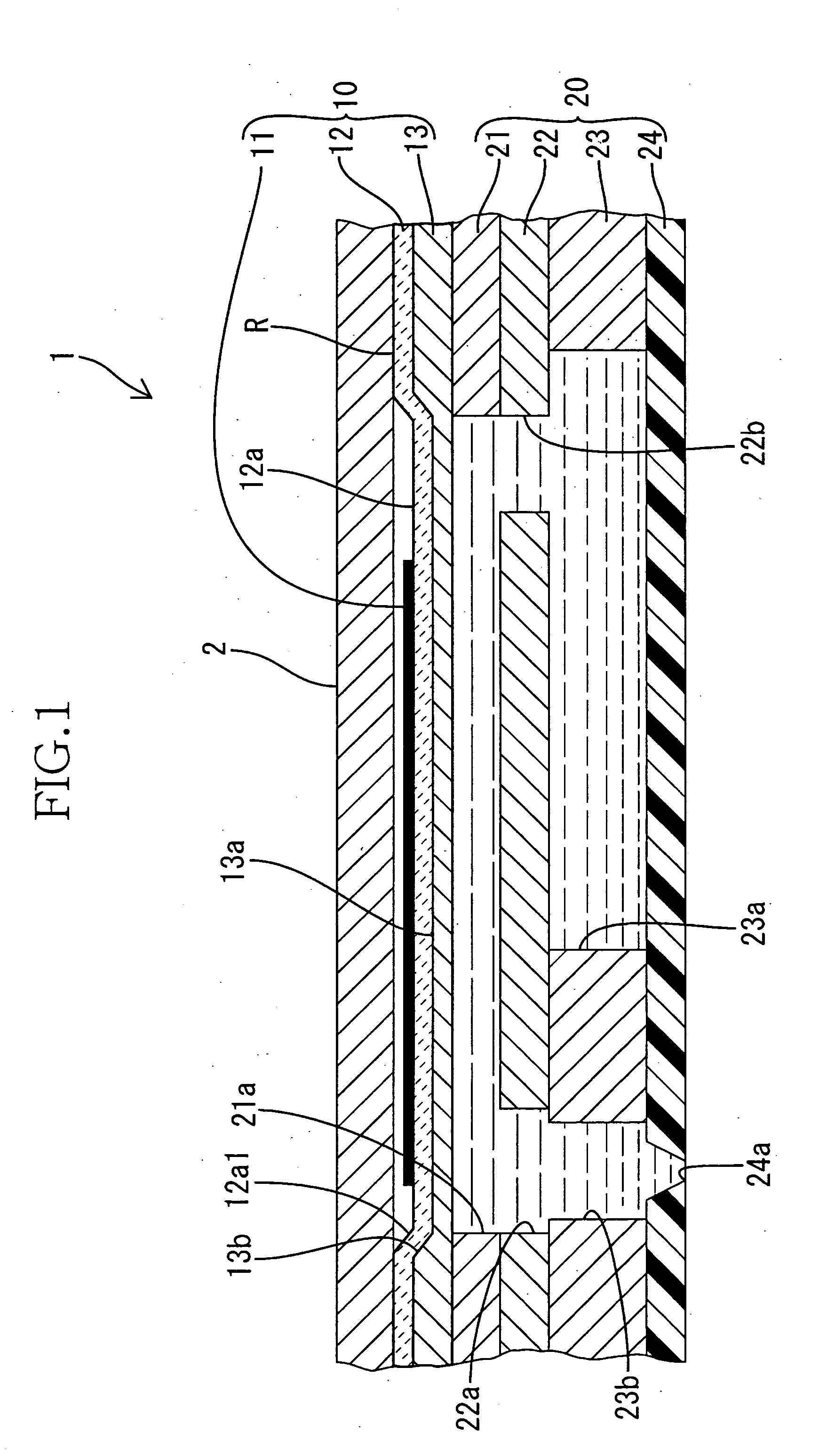
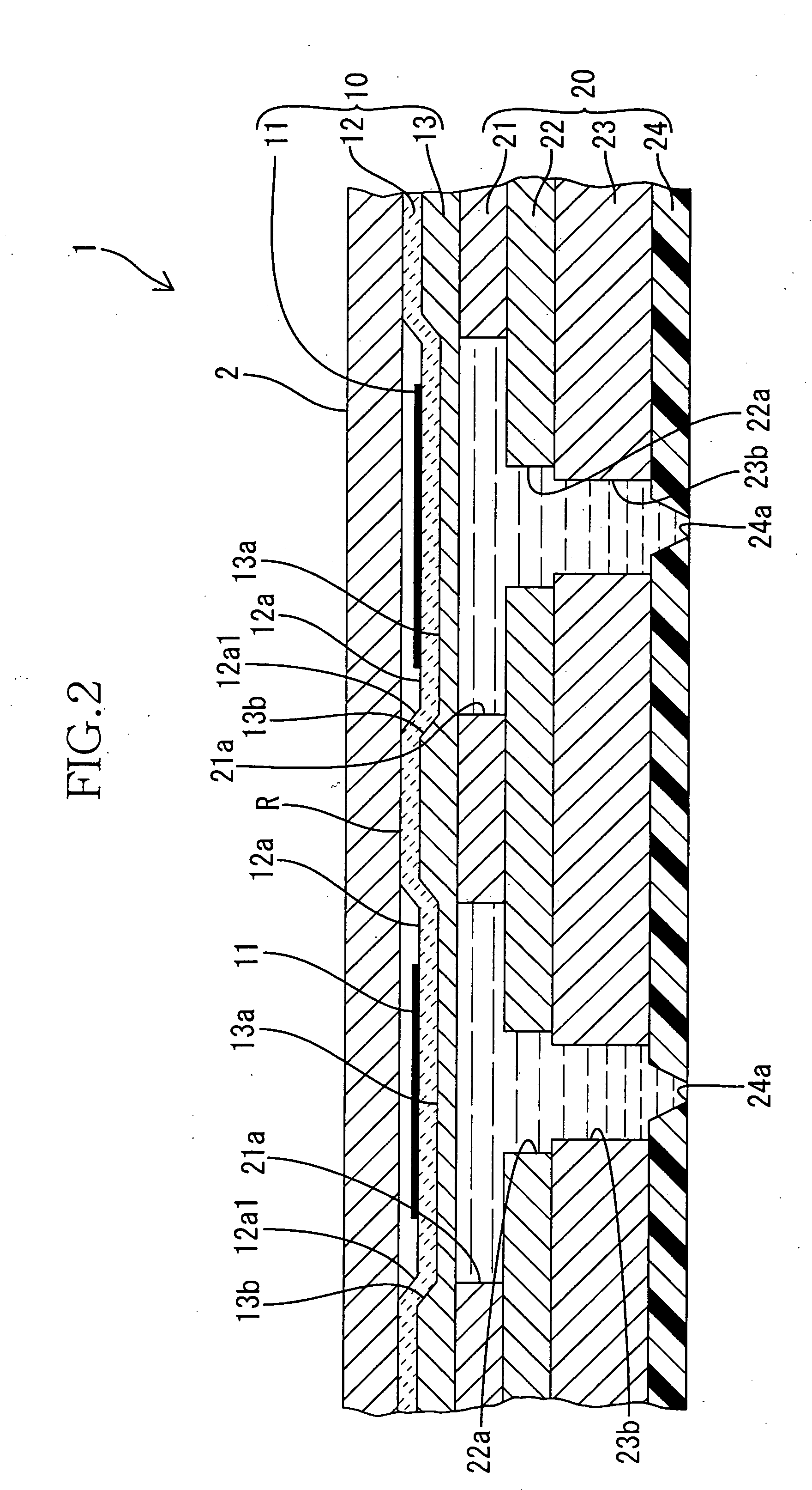
[0017] Referring first to FIGS. 1-4, there will be described a liquid delivering device 1 constructed according to the invention. It is noted that the left half of FIG. 3 corresponds to a plan view of the liquid delivering device 1 and that the right half of FIG. 3 corresponds to a cross sectional view of the device 1 taken in a plane having the same height as pressure chambers 21a.
[0018] The liquid delivering device 1 includes a cavity unit in the form of a passage defining unit 20 in which a plurality of pressure chambers 21a are arranged, and a piezoelectric actuator unit 10 which has a plate-like shape as a whole and which is fixedly superposed on the passage defining unit 20. In the passage defining unit 20, there are arranged a plurality of cavities in the form of pressure chambers 21a for accommodating a liquid which is to be eventually ejected from the device 1. The pressure chambers 21a open in an upper surface of the passage defining unit 20, and the openings of the respe...
second embodiment
[0035] Referring next to FIGS. 5 and 6, there will be described a liquid delivering device 1A which is constructed according to the invention. In FIGS. 5 and 6, the same reference signs as used in FIGS. 1-4 are used to identify the same components or elements, which will not be described to avoid redundancy of description.
[0036] This liquid delivering device 1A is substantially identical with the above-described liquid delivering device 1 of the first embodiment, except that the backup plate 2 is replaced by a backup plate 4 which has through-holes 4a located in its portions corresponding to or aligned with the respective pressure chambers 21a in the vertical direction. Each of the through-holes 4a has a generally oval shape which is slightly larger than that of the corresponding pressure chamber 21a, as viewed in the plan view of FIG. 6. Like the backup plate 2 of the device 1 of the first embodiment, the backup plate 4 is fixed or jointed, at its portions corresponding to peripher...
third embodiment
[0058] In the above-described third embodiment, the backup plate 6 has the recesses 6a each having a cross sectional area substantially equal to or slightly larger than that of the corresponding pressure chamber 21a as viewed in the plan view. However, these recesses 6a may be replaced with through-holes formed through the backup plate 6.
PUM
 Abstract
Description
Claims
Application Information