Peristaltic pump with a moveable pump head

Active Publication Date: 2005-03-31
BAUSCH & LOMB INC
View PDF51 Cites 38 Cited by
  • Summary
  • Abstract
  • Description
  • Claims
  • Application Information

AI Technical Summary

Problems solved by technology

This is somewhat cumbersome, time consuming, and inconvenient for a user.
This method is also convenient for the user but has a potential drawback in that the backing plate of the cartridge typically does not cooperate with the pump head over a sufficiently large radius.
This relatively small radius of interaction can lead to unwan

Method used


Image

  • Peristaltic pump with a moveable pump head
  • Peristaltic pump with a moveable pump head
  • Peristaltic pump with a moveable pump head

Examples


Embodiment Construction

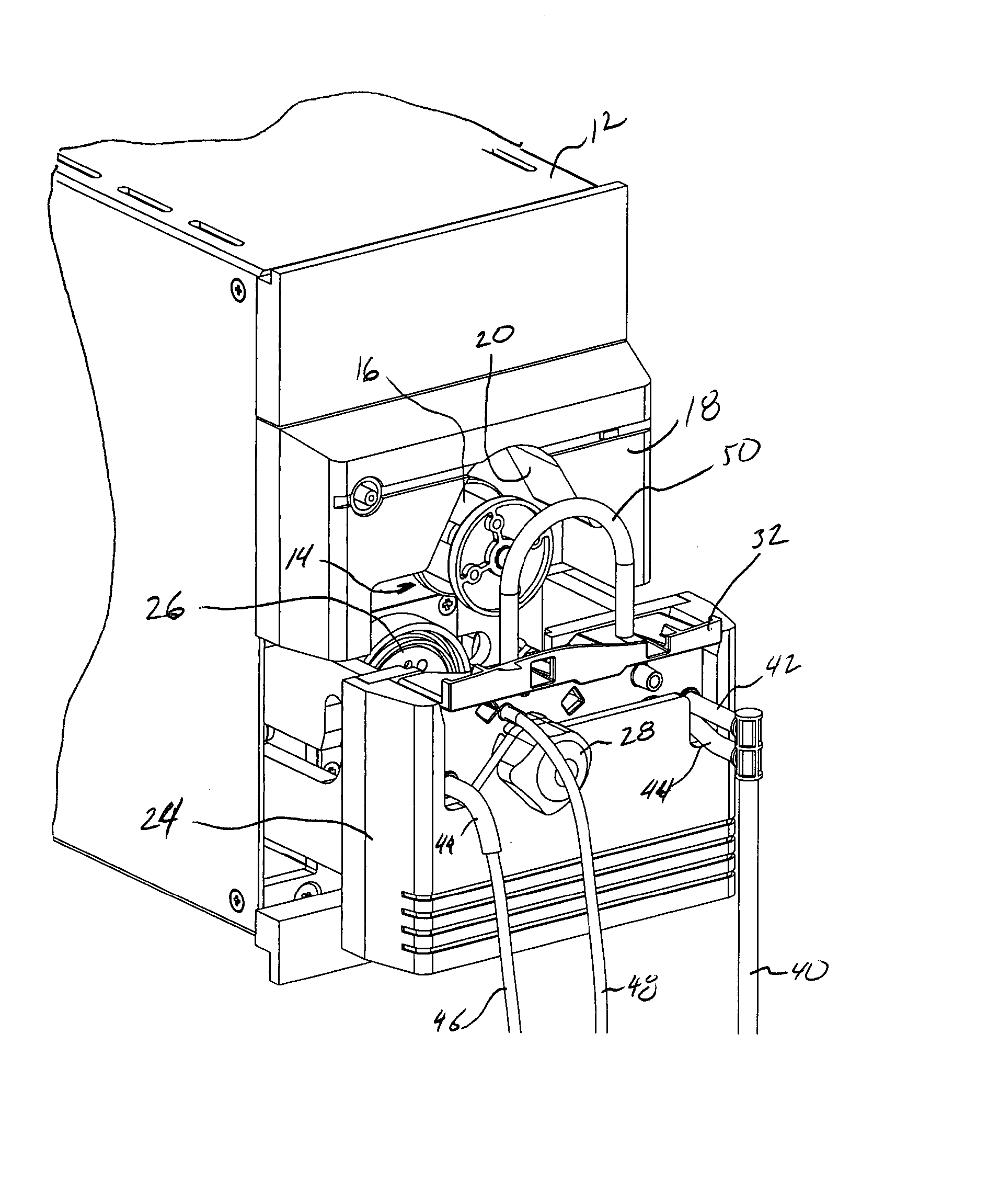
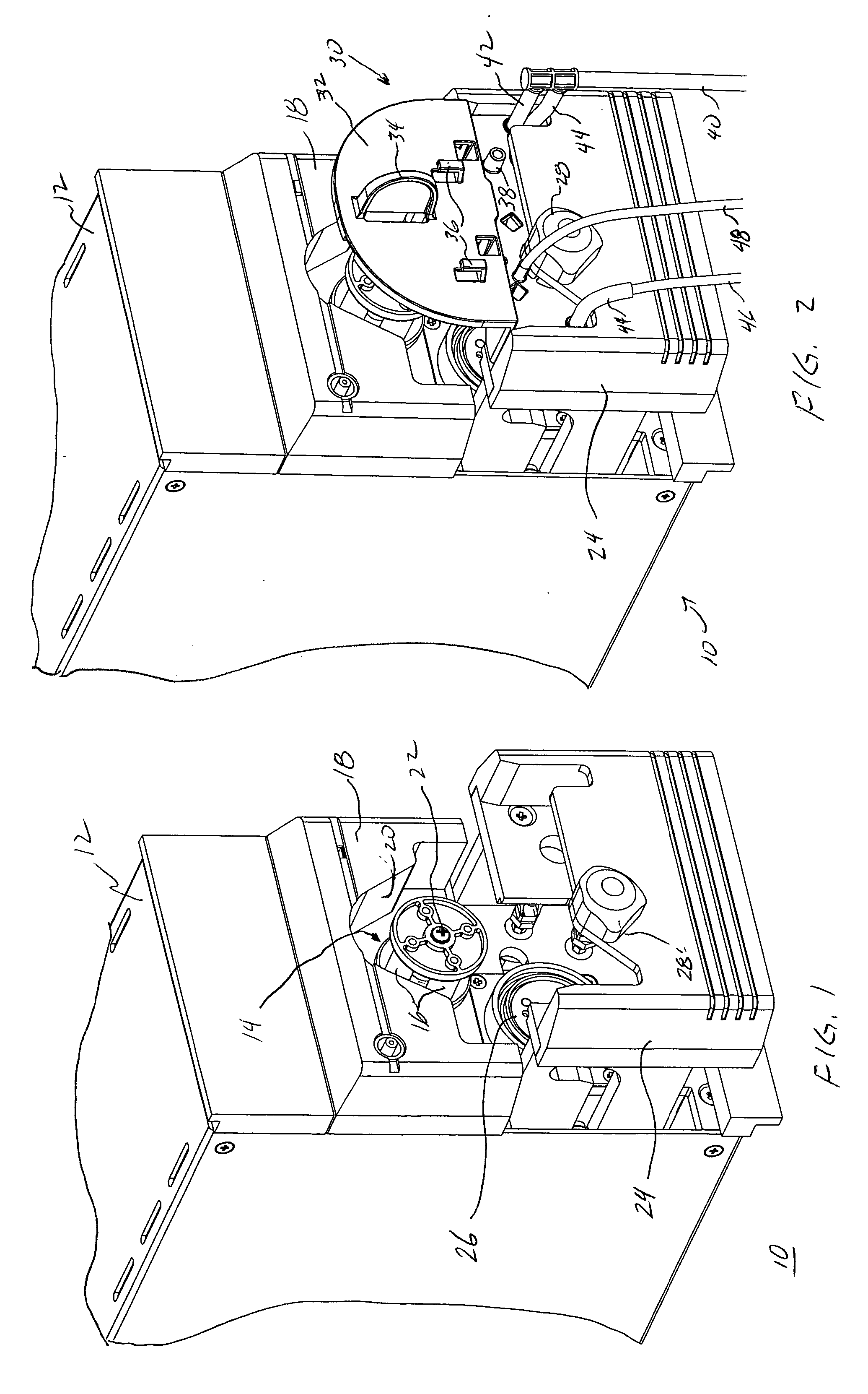
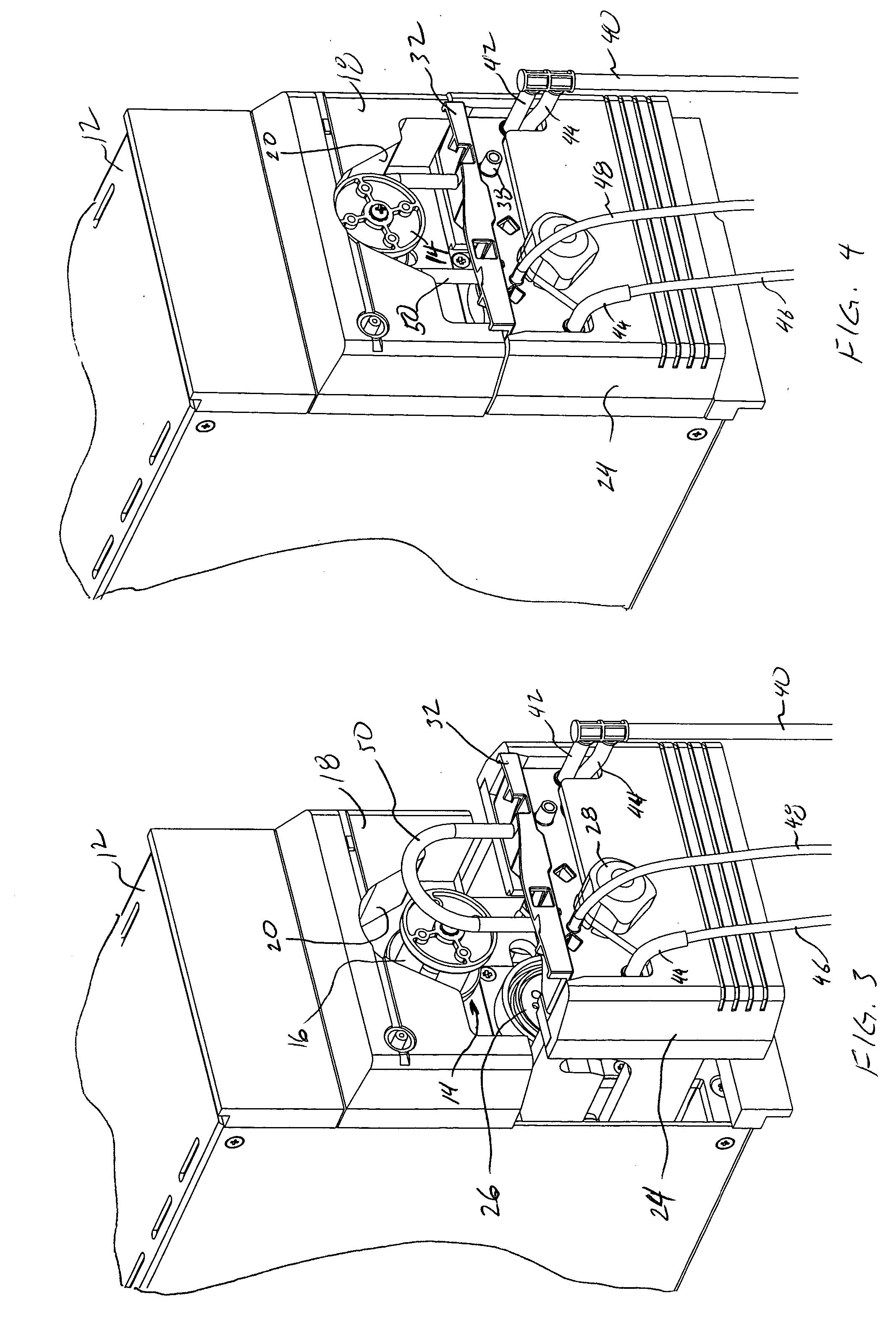
[0023]FIG. 1 shows a partial perspective view of a peristaltic pump 10 for use in ophthalmic surgery, in accordance with the present invention. A housing 12 includes a pump head 14 having a plurality of rollers 16 held within and extending from the housing 12. A backing plate 18 is attached to the housing 12 and cooperates with the pump head 14 to pinch a length of tubing between the rollers 16 and backing plate surface 20. Pump head 14 moves relative to the housing 12 and the backing plate 18, as described in detail below. In FIG. 1, pump head 14 is shown in an open position and ready for the insertion of a pump cartridge, as described below.

[0024] Pump head 14 is preferably connected to a motor (not shown) and the pump head 14 causes rollers 16 to rotate about a central axis 22 of the pump head 14, such that the rollers 16 and the backing plate 18 cooperate to compress or pinch a length of surgical tubing and peristaltically pump fluids from a surgical site through the tubing to ...


PUM


Abstract

A peristaltic pump 10 for use in ophthalmic surgery includes a housing 12, a pump head 14 having plurality of rollers 16 held within the housing 12, and a backing plate 18 attached to the housing 12. The pump head14 moves relative to the housing 12 and backing plate 18.

Description

BACKGROUND OF THE INVENTION [0001] 1. Field of the Invention [0002] The present invention is related to surgical pumps, and particularly to peristaltic pumps for use in ophthalmic surgery. [0003] 2. Description of Related Art [0004] It is well known to use pumps in surgery, including ophthalmic surgery, to pump aspirant (fluids and tissue) from a surgical site, such as a patient's eye. Such pumps vary in the method used to pump aspirant including venturi pumps, scroll pumps, and peristaltic pumps. [0005] Peristaltic pumps are well known in ophthalmic surgery and typically include a rotating pump head with a plurality of rollers spaced about the circumference of the pump head. These rollers typically cooperate with a backing plate to pinch closed a small section of tubing placed between the rollers and backing plate. As the pump head rotates, the rollers revolve and provide a continuous pinch point along a length of tubing. The rollers and backing plate are constructed that multiple ...

Claims


Application Information

Patent Timeline
IPC IPC(8): F04B43/12
CPCF04B43/1276F04B43/1253F04B43/1284F04B53/16F05B2210/11Y10S417/00A61M1/92A61M1/80
Inventor MITTELSTEIN, MICHAELSORENSEN, JOHN T.MIRHASHEMI, SOHEILAGERG, JAMESSCHAUER, ROBERT
Owner BAUSCH & LOMB INC
Why Eureka
Try Eureka