Wire connector

a wire connector and connector technology, applied in the direction of unstripped conductor connection apparatus, coupling device connection, contact member penetration/cutting of insulation/cable strand, etc., can solve the problem of inconvenient us

Inactive Publication Date: 2005-03-31
HUNG PAO TIEN
View PDF3 Cites 10 Cited by
  • Summary
  • Abstract
  • Description
  • Claims
  • Application Information

AI Technical Summary

Benefits of technology

[0009] A further objective of the present invention is to provide a wire connector, wherein the locking hooks of the guide plates of the upper cover and the lower cover are locked in the r

Problems solved by technology

Thus, the cover 12 cannot be moved into the main body 11 easil

Method used


Image

  • Wire connector
  • Wire connector
  • Wire connector

Examples


Embodiment Construction

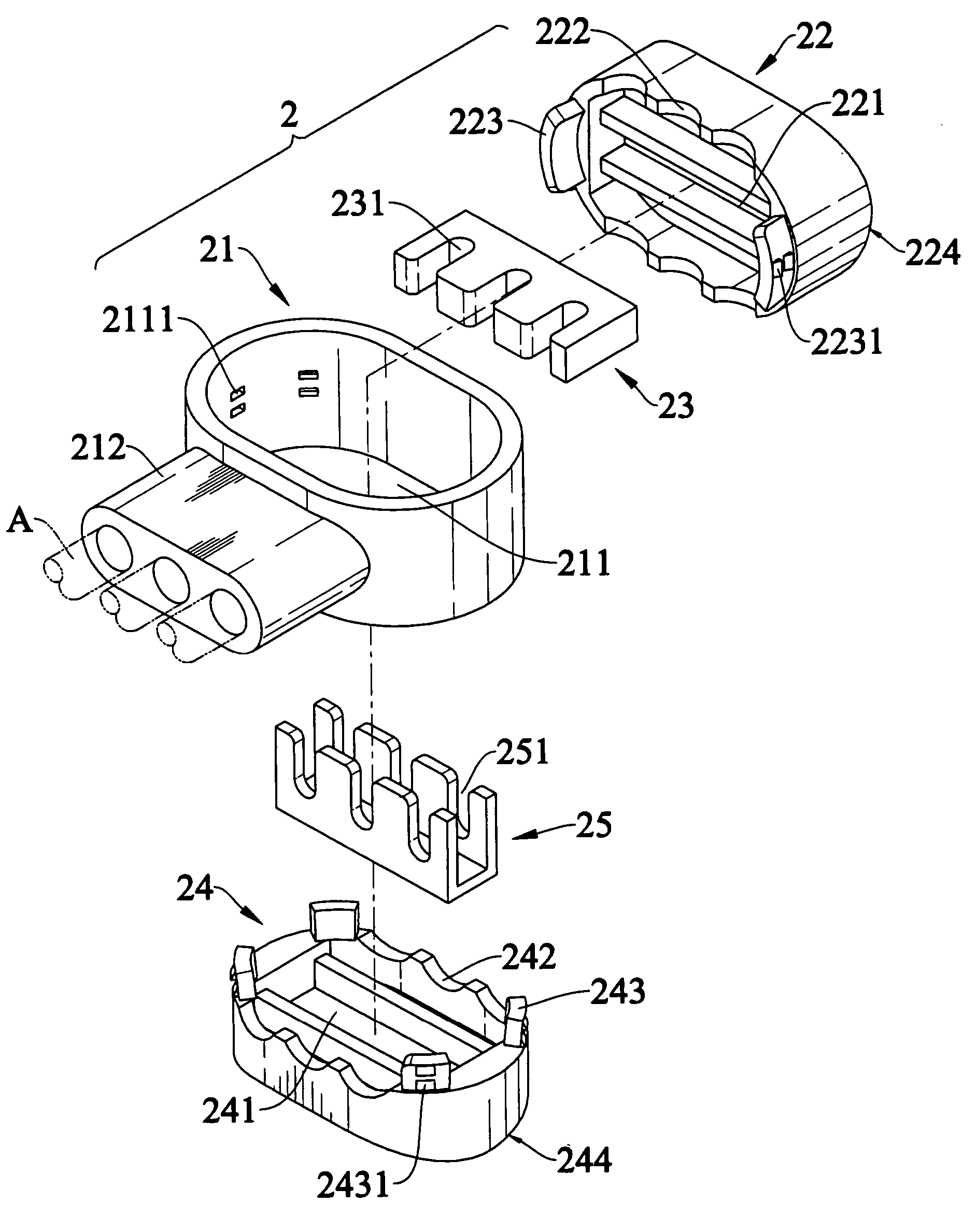
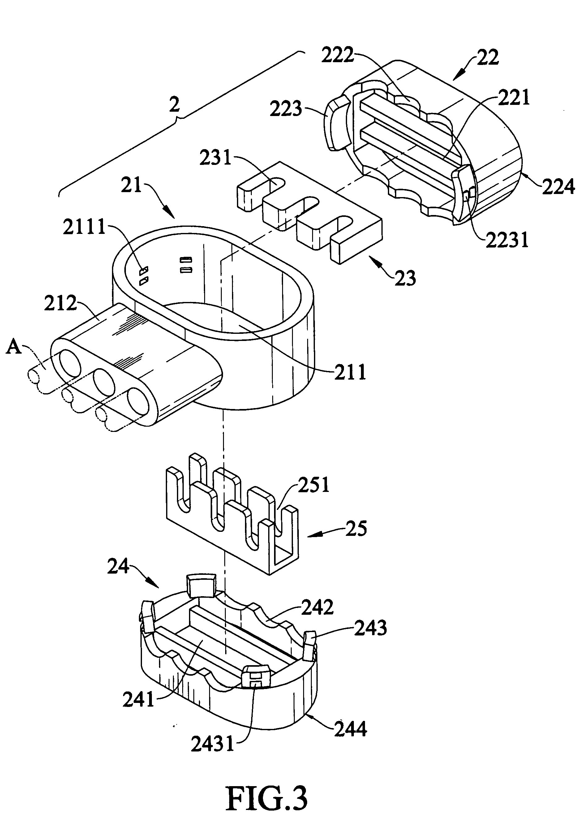
[0025] Referring to the drawings and initially to FIGS. 3-5, a wire connector 2 in accordance with the preferred embodiment of the present invention comprises a main body 21, an upper cover 22, an upper cutter 23, a lower cover 24, and a lower cutter 25.

[0026] The main body 21 has an inner wall formed with an oblong receiving chamber 211. The receiving chamber 211 of the main body 21 has a periphery formed with a plurality of insertion recesses 2111. The main body 21 has an outer wall formed with a protruding receiving block 212 connected to the receiving chamber 211 of the main body 21 for passage of a plurality of electric wires A.

[0027] The upper cover 22 is mounted in an upper portion of the receiving chamber 211 of the main body 21 and has an inside formed with a channel 221. The upper cover 22 has two side walls each having a lower portion formed with a plurality of arc-shaped grooves 222. The upper cover 22 has two ends each having a lower portion formed with a guide plate ...


PUM


Abstract

A wire connector includes a main body, an upper cover, an upper cutter, a lower cover, and a lower cutter. Thus, the oblique jaw portions of the pliers are closely urged on the oblique faces of the action portions of the upper cover and the lower cover, so that the upper cover and the lower cover are pressed by the pair of pliers to move into the receiving chamber of the main body smoothly and conveniently without incurring deflection.

Description

BACKGROUND OF THE INVENTION [0001] 1. Field of the Invention [0002] The present invention relates to a wire connector for connecting an electric wire, and more particularly to a wire connector that facilitates the user's operation. [0003] 2. Description of the Related Art [0004] A conventional wire connector 1 in accordance with the prior art shown in FIGS. 1 and 2 comprises a main body 11, and a cover 12 movably mounted on the main body 11. The main body 11 has an outer wall formed with a protruding receiving block 111 connected to the inside of the main body 11 for passage of a plurality of electric wires A. The cover 12 is provided with a cutter 121 aligning with the electric wires A. In operation, the jaws B1 of a pair of pliers B are pressed on the cover 12 and the main body 11 to move the cover 12 into the main body 11, so that the cutter 121 of the cover 12 will pierce the outer layers of the electric wires A, thereby conducting the cores A1 of all of the electric wires A. [0...

Claims


Application Information

Patent Timeline
IPC IPC(8): H01R4/24H01R43/01
CPCH01R43/015H01R4/2433
Inventor HUNG, PAO-TIEN
Owner HUNG PAO TIEN
Why Eureka
Try Eureka