Bow-facing rowing system

a rowing system and bow-facing technology, applied in waterborne vessels, marine propulsion, vessel construction, etc., can solve the problems of accelerating, complex and necessarily expensive gear system, and obvious inferiority of the inventions listed above that do not provide feathering, so as to improve the needs of recreational rowers, reduce acceleration, and simple car-top boat

Inactive Publication Date: 2005-03-31
BLEICKEN ERIC VAUGHN
View PDF2 Cites 9 Cited by
  • Summary
  • Abstract
  • Description
  • Claims
  • Application Information

AI Technical Summary

Benefits of technology

[0019] The object of the Bow-Facing Rowing System is to provide an improved forward facing means to row a shorter, low-volume boat that will provide the recreational and exercise rower with a simple, low-maintenance, car-top boat.
[0020] The Bow-Facing Rowing System allows the operators weight to remain at a fixed point in the boat and still have essentially the same arm/leg/back motions that would be found in a conventional sliding-seat rowing system. A disadvantage of the sliding seat and the resulting shifting weight forward and backward is that the boat tends to porpoise, or dive and bob, with the moving center of gravity. This porpoising has been traditionally offset by the production of very long boats (26 feet). By fixing the operators seat and moving the legs instead, the same rowing motions are executed but the porpoising problem is resolved and a true car top boat (16 feet) can be built to better satisfy the needs of the recreational rower.
[0021] A rowboat naturally moves faster through the water during the power stroke and slower during the return stroke. With a sliding seat rowing system there is a second factor involved. The rower is generally much heavier than the rowboat. As a result, his/her momentum tends to move steadily and the rowboat experiences positive and negative accelerations do to the shifting weight. With the proposed fixed-seat/sliding-feet concept, the boat and rower will act as a single mass and reduce those accelerations.
[0022] With prior articulating oars that use a fixed outrigger...

Problems solved by technology

This is an awkward and largely unusable approach in recreational and racing rowboats where skimming the surface with a feathered oar on the return stroke adds stability and reduces resistance from wind and wave.
Those inventions listed above that do not provide feathering are obviously inferior and a detailed discussion is unnecessary.
Noggle U.S. Pat. No. 4,738,643 comes closest to addressing the feathering problem but offers a complex and necessarily expensive system of gears.
It appears that the rotation of the handgrip will erroneously rotate the blade in the same direction.
The Dupont design uses control rods and a complex system of levers that is likely to be heavy and cumbersome, and exhibit racking pro...

Method used


Image

  • Bow-facing rowing system
  • Bow-facing rowing system
  • Bow-facing rowing system

Examples


Embodiment Construction

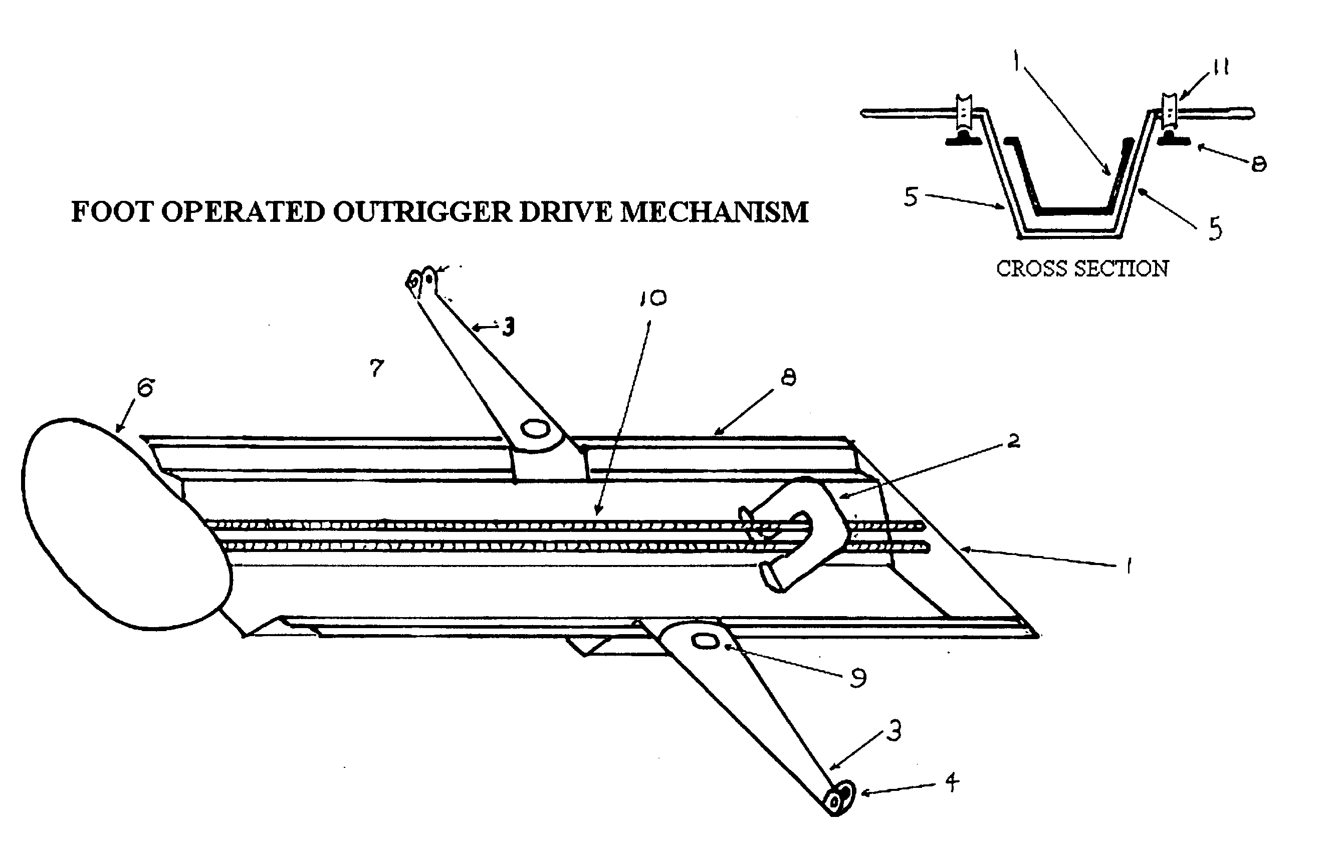
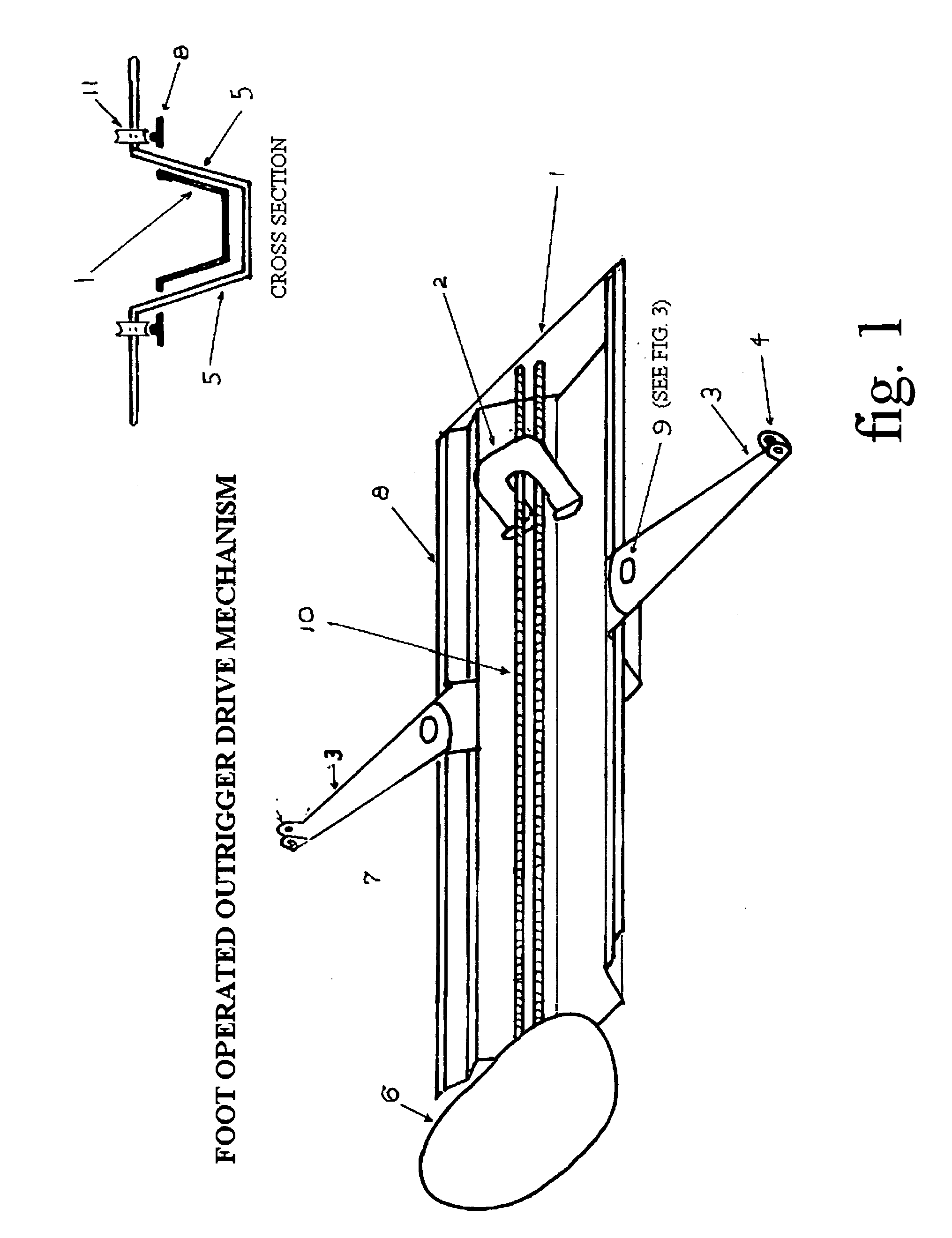
[0035] Bow Facing Rowing System is comprised of the foot operated, outrigger drive mechanism (FIGS. 1 and 2), articulating oars (FIGS. 3 and 4) and self-feathering blade (FIGS. 5 and 6).

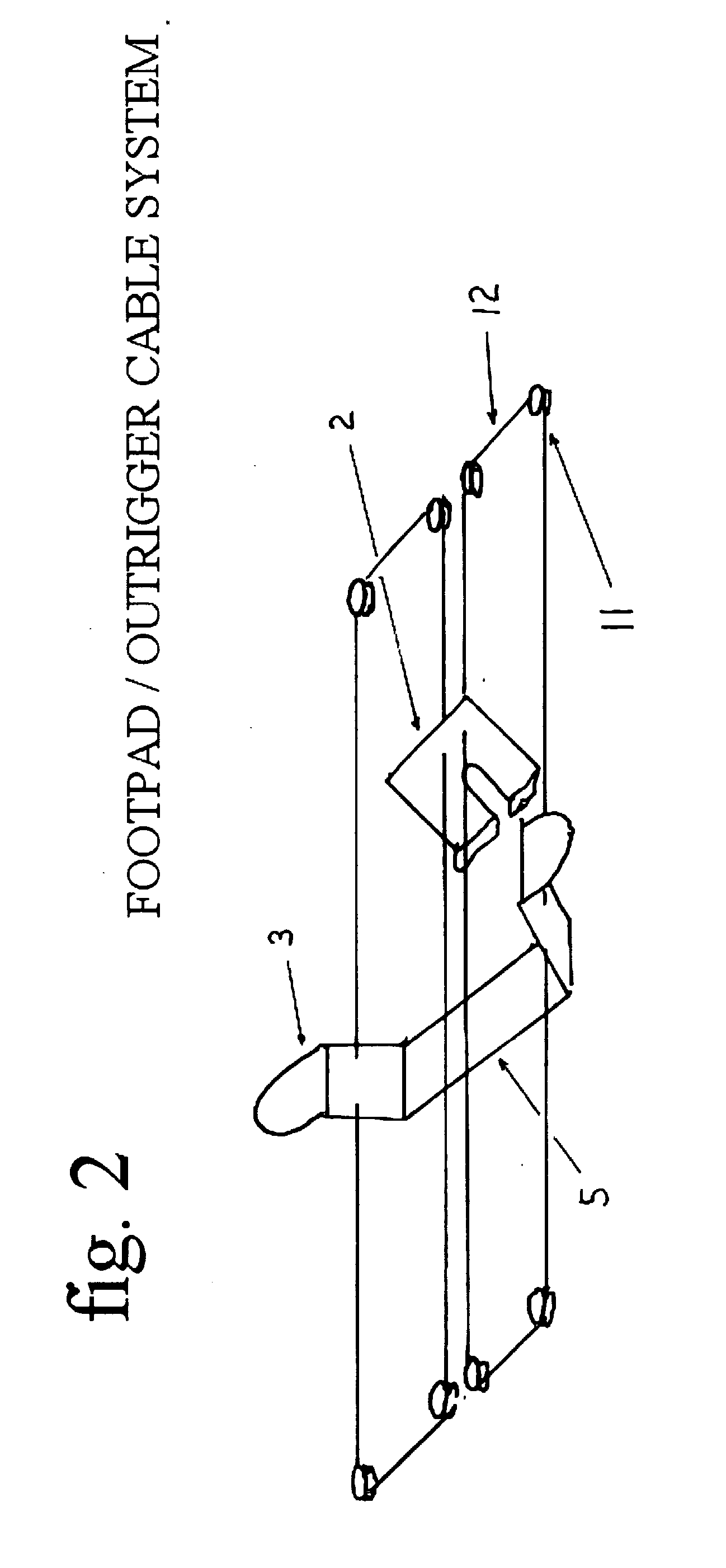
[0036] Foot operated, outrigger drive mechanism: A molded cowling 1 provides the framework for said mechanism. Tracks 8 are mounted along the port and starboard gunnels on which the lower member of the outrigger assembly 5 rides. The depth of the cowling is about seven inches and is wide enough for both of the rower's feet to be comfortably positioned side by side on the footpad 2. Between the feet is a rail 10 on which the footpad 2 rides. This footpad uses a system of rails and sheaves for minimum friction. A fixed seat 6 is mounted at the rear of the cowling. The lower member of the outrigger assembly 5 is connected to the footpad 2 with a system of sheaves 11 and cables 12 that cause the outrigger 3 to travel in the opposite direction as the footpad 2. Said cables 12 are mounted outside of the c...


PUM


Abstract

A rowing device with articulating oars FIG. 4 that are connected to outriggers FIG. 1 at the point of articulation. While the rower sits on a fixed seat 6, said outriggers 4 are foot operated 2 and function in the opposite direction as the feet through a system of cables 12 and sheaves 11.

Description

CROSS REFERENCE TO RELATED APPLICATIONS [0001] U.S. Cl. 416, subclass 74 [0002] U.S. Cl. 440, subclasses 101, 102, 103, 104, 105 [0003] U.S. Cl. D12, subclass 215 and 317 [0004] References Cited: Articulating Oar Gearing1,609,3307 / 12 / 1926Thibodeau1,120,94415 / 12 / 1914Koble2,033,63710 / 3 / 1936Kaiser2,565,71428 / 8 / 1951Anderson5,112,26112 / 4 / 1992Humphrey6,113,4479 / 5 / 2000Roy et. al.4,738,6434 / 19 / 1988Noggle0,517,99910 / 5 / 1894Burns0,355,87911 / 1 / 1887McGeeD252,62514 / 8 / 1979WhiteD235,86515 / 7 / 1975Bellis6,083,0664 / 7 / 2000Wright4,943,2506 / 1990duPontOutrigger-Foot Operated  89,6635 / 1869Heroux5,647,7826 / 15 / 1997Henry5,215,4821 / 1 / 1993Henry4,889,50926 / 12 / 1989Pohlus5,685,75011 / 11 / 1997Rantilla6,109,98829 / 8 / 2000Dunn, Jr.4,867,71919 / 9 / 1989duPont4,383,83017 / 5 / 1983Cartwright3,828,2128 / 16 / 1988KrollPfeifer2,101,946 (UK)28 / 1 / 83Waugh et. al.2,099,773 (UK)5 / 6 / 1981WollonerAuto-feathering Blade4,943,25024 / 7 / 1990duPont5,248,27228 / 9 / 1993duPont3,215,48224 / 4 / 1973Trull2,209,723 (UK)9 / 8 / 1988Witchell4,406,438 (Germany)11 / 9 / 198...

Claims


Application Information

Patent Timeline
IPC IPC(8): B63H16/02B63H16/10
CPCB63H16/102B63H16/02
Inventor BLEICKEN, ERIC VAUGHN
Owner BLEICKEN ERIC VAUGHN
Why Eureka
Try Eureka