Constant velocity joint

a constant velocity, joint technology, applied in the direction of yielding couplings, rotary machine parts, couplings, etc., can solve the problems of inability to make constant the depth of the ball groove is inevitably reduced, and the known uf-type constant velocity joints may suffer, etc., to achieve enhanced freedom in the design of the joint, the effect of reducing size and weigh

Inactive Publication Date: 2005-03-31
TOYOTA JIDOSHA KK +1
View PDF9 Cites 18 Cited by
  • Summary
  • Abstract
  • Description
  • Claims
  • Application Information

AI Technical Summary

Benefits of technology

[0022] In the constant velocity joint constructed as described above, a load applied to each of the balls located in the relief groove portions during torque transmission can be made smaller than a load applied to the balls located in the other portions of the ball grooves, thus assuring sufficiently high durability even if the relief groove

Problems solved by technology

However, the known UF-type constant velocity joints may suffer from the following problems caused by the increase in the maximum joint angle.
If the ball grooves are formed to extend substantially straight in the outer race, the depth of the ball grooves cannot be made constant, and some portions of the ball grooves inevitably have a reduced depth.
It is thus difficult to ensure sufficiently high durability at port

Method used


Image

  • Constant velocity joint
  • Constant velocity joint
  • Constant velocity joint

Examples


Embodiment Construction

[0033] One exemplary embodiment of the invention will be described in detail with reference to the accompanying drawings.

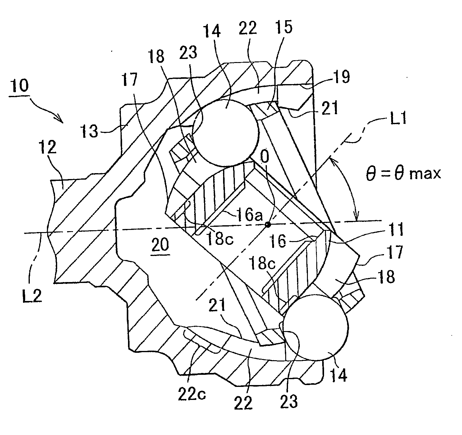
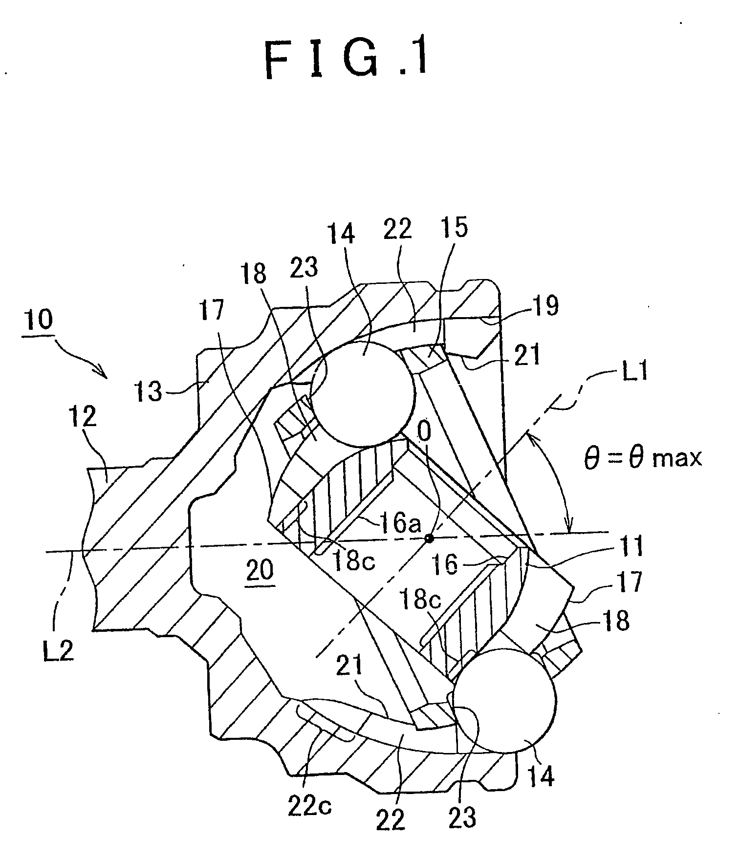
[0034] A constant velocity joint 10 according to the embodiment of the invention as shown in FIG. 1 generally includes an inner race 11 connected to an end portion of a driving shaft (not shown), and an outer race 13 connected integrally to a driven shaft 12. The constant velocity joint 10 further includes a plurality of balls 14 (i.e., six balls in this embodiment) that are interposed between the inner race 11 and the outer race 13 and are arranged to transmit torque between the inner and outer races 11, 13, and a cage 15 for holding these balls 14. FIG. 1 shows a state of the constant velocity joint 10 in which the joint angle 0 is equal to the maximum angle θmax.

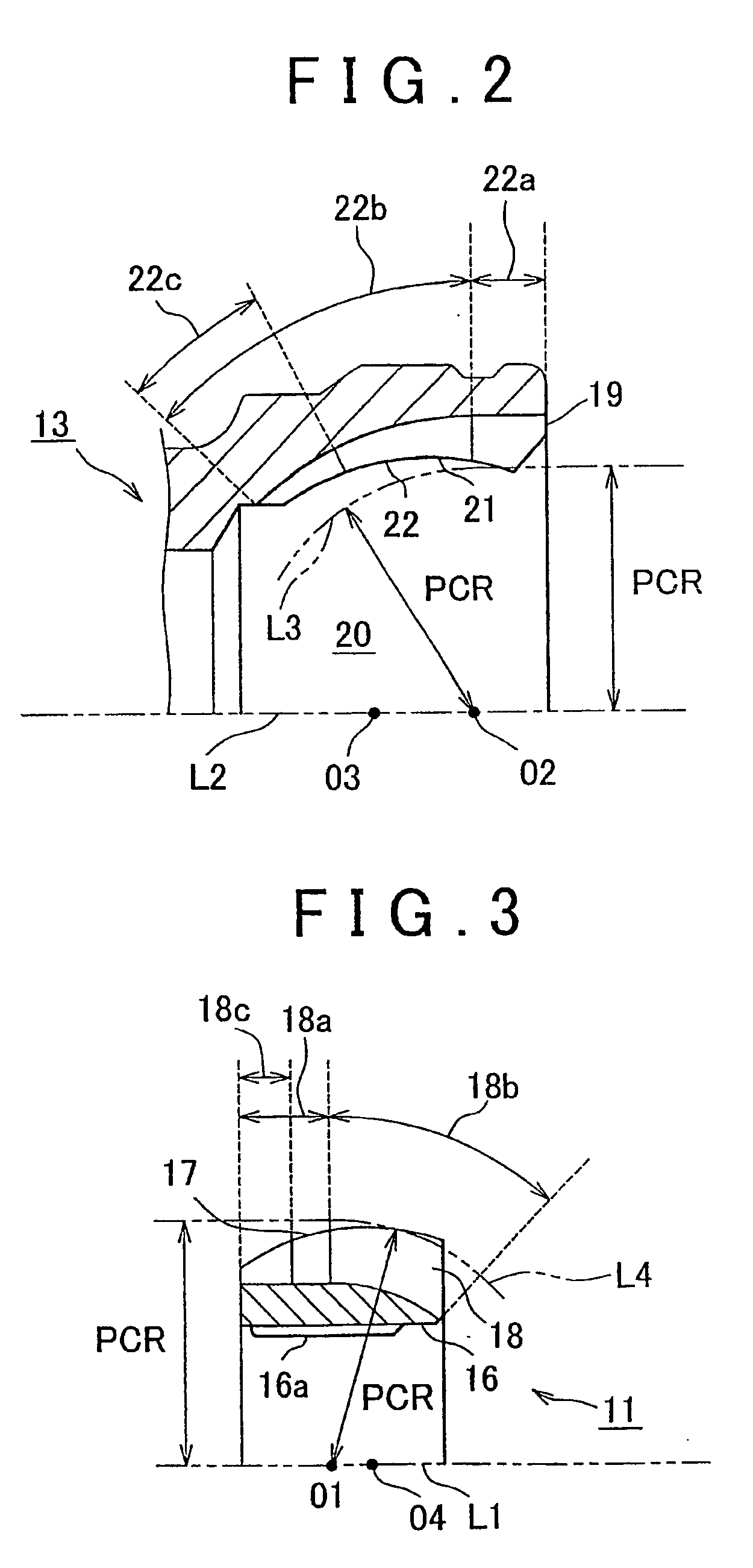
[0035] A through-hole 16 is formed in the inner race 11 to extend through the inner race 11 in the direction of its rotation axis L1, as shown in FIG. 1. A spline 16a extending in the direction of the...


PUM


Abstract

A constant velocity joint includes an outer race having a plurality of ball grooves formed in an inner spherical surface thereof, which ball grooves extend in a direction of a rotation axis of the outer race, an inner once having a plurality of ball grooves formed in an outer spherical surface thereof, which ball grooves extend in a direction of a rotation axis of the inner race and are paired with the ball grooves of the outer race, and a plurality of balls disposed between the ball grooves of the outer race and the hall grooves of the inner race. In the constant velicity joint, the hall grooves of at least one of the outer race and the inner race are partially formed wit relief profiles to provide a plurality of relief groove portions such that a load applied to each of the balls located in the relief groove portions during torque transmission between the inner race and the outer race is smaller than a load applied to each of the balls located in the other portions of the ball grooves.

Description

BACKGROUND OF THE INVENTION [0001] 1. Field of the Invention [0002] The invention generally relates to a constant velocity joint, and more particularly to a ball-type constant velocity joint having a plurality of balls captured between an inner race and an outer race of the joint. [0003] 2. Description of Related Art [0004] In front-wheel drive vehicles and four-wheel drive vehicles, for example, constant velocity joints are generally used in coupling portions between front wheels serving as steering / driving wheels and drive shafts. Such a constant velocity joint allows changes in the joint angle between a driving shaft and a driven shaft connected to the joint, while permitting the driving shaft and the driven shaft to rotate at an equal angular velocity. As one type of the constant velocity joints, a ball-type constant velocity joint is known in which a plurality of balls are captured between an inner race and an outer race of the joint such that torque is transmitted through cont...

Claims


Application Information

Patent Timeline
IPC IPC(8): F16D3/223F16D3/2237
CPCF16D3/2237Y10S464/906F16D2003/22309F16D3/223
Inventor MATSUMOTO, TAKUMIMATSUDA, TAKASHINIMURA, TETSUOMATSUURA, KOUICHISUZUKI, SATOSHINAKAI, SHINJI
Owner TOYOTA JIDOSHA KK
Why Eureka
Try Eureka