
Electronic endoscope apparatus

Inactive Publication Date: 2005-03-31
FUJI PHOTO OPTICAL CO LTD
View PDF7 Cites 19 Cited by
  • Summary
  • Abstract
  • Description
  • Claims
  • Application Information

AI Technical Summary

Benefits of technology

[0014] According to such electronic endoscope apparatus, the electronic scope can be removed from the processor unit regardless of whether the output processing of the digital image to the external equipment is completed. Hence, it becomes possible to smoothly perform the washing of the electronic scope after endoscopy is ended, the connection of another electronic scope for the following examination, and the like.
[0015] In addition, even when the CCD drive pulse is being outputted or communicating between with the electronic scope .is being performed, scope power can be disconnected safely. Hence, it becomes possible to prevent amalfunction or a failure of the apparatus, mixing of noise, etc.

Problems solved by technology

Nevertheless, since the size of one high-resolution image is large (an amount of data per image is large), digital image processing time (transmission time) becoming long.
Hence, since the processing of outputting a digital image signal to external equipment is not completed in spite of endoscopy being ended, there arises a problem that the electronic scope cannot be removed from the processor unit.
That is, although washing and disinfection of the electronic scope must be performed and connection of another electronic scope is necessary in preparation for the next examination after endoscopy is ended, the next operation cannot be performed smoothly when the output processing of the digital image signal to the external equipment is not completed.

Method used


Image

  • Electronic endoscope apparatus
  • Electronic endoscope apparatus
  • Electronic endoscope apparatus

Examples


Embodiment Construction

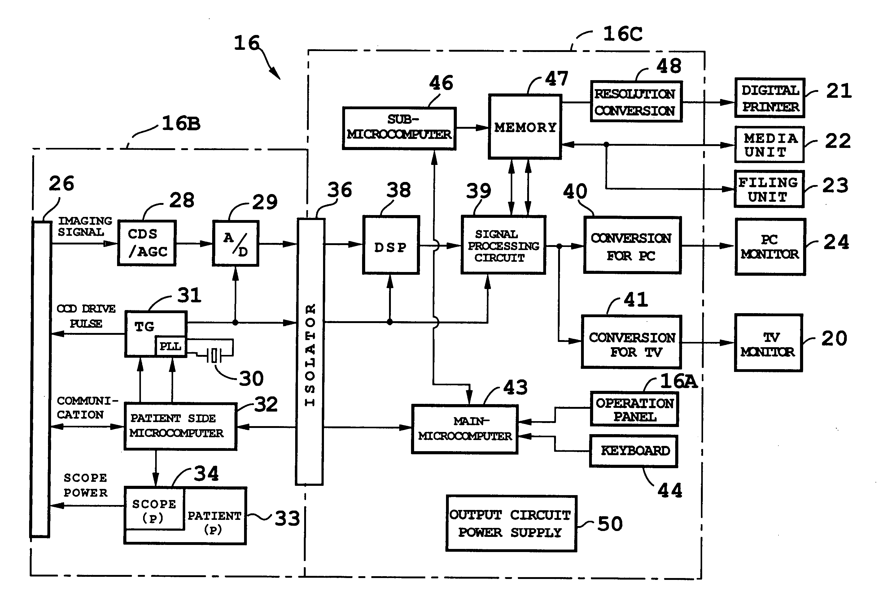
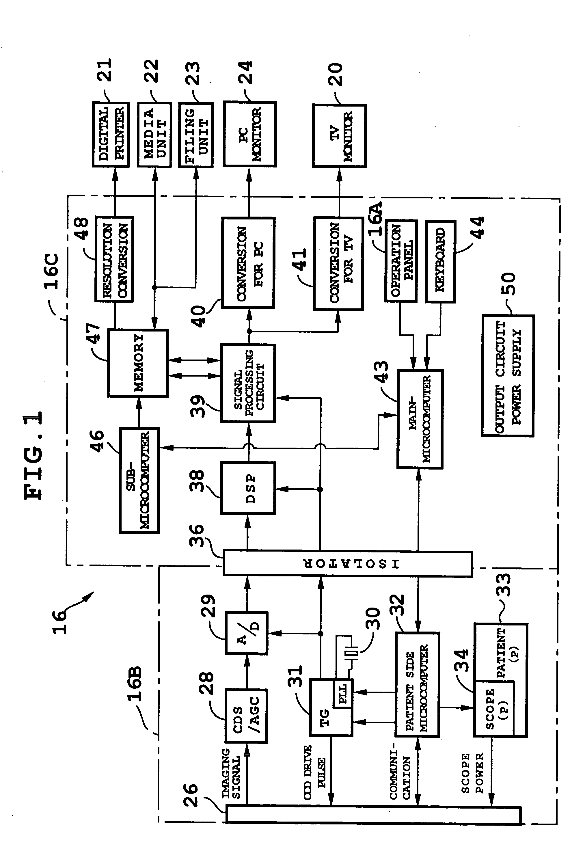
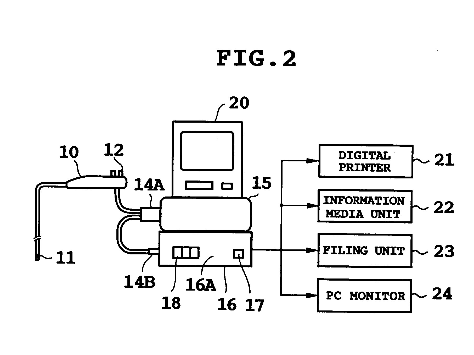
[0018]FIGS. 1 and 2 show the structure of an electronic endoscope apparatus according to an embodiment, and the entire structure will be explained first. As shown in FIG. 2, a CCD 11 which is a solid-state image pickup device is provided in an end section of an electronic scope (electronic endoscope) 10. As this CCD 11, CCDs with various kinds of pixel counts are mounted. In an operation unit of this electronic scope 10, control switches such as a freeze / record button 12 are located. This electronic scope 10 is connected not only to light equipment 15 through a light guide connector 14A, but also to a processor unit 16 through a signal / power supply line connector 14B. The light of the above-mentioned light equipment 15 is supplied to the end section through a light guide located in the electronic scope 10. An object is imaged by the above-mentioned CCD 11 owing to illumination light emitted from this end section.

[0019] In the front control (operation) panel 16A of the processor uni...


PUM


Abstract

An electronic endoscope apparatus has the structure that an electronic scope is detachably connected to a processor unit. This processor unit comprises image storage memory which stores an object image imaged by a CCD, a signal processing circuit for outputting this image to external equipment, a scope power-off operation switch located separately from a main-power switch are provided. Only a scope power supply unit which supplies power to the electronic scope is turned off by this scope power-off switch. At this time, when a CCD drive pulse is being outputted or when communication between with the electronic scope is being performed, the outputting of this CCD drive pulse or the communication is stopped, and thereafter,the scope power supply unit is turned off. Thereby, the electronic scope can be removed from the processor unit which is outputting an image signal.

Description

BACKGROUND OF THE INVENTION [0001] The application claims the priority of Japanese Patent Applications No. 2003-336718 filed on Sep. 29, 2003 which is incorporated herein by reference. [0002] 1. Field of the Invention [0003] The present invention relates to an electronic endoscope apparatus, and in particular, to the construction of an electronic endoscope apparatus where an imaging signal obtained by a solid state image pickup device of an electronic scope is outputted to a processor unit, and this processor unit forms a digital imaging signal for outputting the imaging signal to external digital processing equipment. [0004] 2. Description of the Related Art [0005] An electronic endoscope apparatus is equipped with a solid-state image pickup device such as a CCD (Charge Coupled Device) in an end section of an electronic scope (electronic endoscope). This CCD images an object on the basis of the illumination of light from light equipment. It becomes possible to display an image of t...

Claims


Application Information

Patent Timeline
IPC IPC(8): A61B1/04G02B23/24
CPCA61B1/042
Inventor HIGUCHI, MITSURU
Owner FUJI PHOTO OPTICAL CO LTD
Learn More