Drill bit and stabilizer gauge

a stabilizer and drill bit technology, applied in the direction of measuring tapes, mechanical measuring arrangements, instruments, etc., can solve the problems of inevitably affecting the external diameter (also referred to as “gauge”) of both parts, affecting the smoothness of the cylindrical nature of the gauge, and causing wear on the external diameter (also referred to as “gauge”)

Inactive Publication Date: 2005-04-07
SAUNDERS ERIC W
View PDF14 Cites 3 Cited by
  • Summary
  • Abstract
  • Description
  • Claims
  • Application Information

AI Technical Summary

Benefits of technology

[0023] Still another object of the invention is to provide a drill bit and stabilizer gauge capable of measuring drill bits and stabilizers having a diameter falling within a predetermined range, in order to avoid the necessity of multiple gauges to measure different drill bit diameters.
[0024] It is an object of the invention to provide improved elements and arrangements thereof for the purposes described which is inexpensive, dependable and fully effective in accomplishing its intended purposes.

Problems solved by technology

Oilfield drilling is one such industrial application where measuring the diameter of drill bits and drill stabilizers plays a pivotal role and proves troublesome with conventional gauges.
Although both bits drill circular holes, they are not smoothly cylindrical in nature.
This rotation of the drill bit and stabilizer inevitably produces wear on the external diameter (also referred to as “gauge”) of both parts caused by friction created from the contact between the bit / stabilizer components and the well bore wall.
Therefore, the resulting diameter approximation is not optimal.
The system does not appear to be appropriate for measuring the diameter of a cylindrical object, the housing having a flat, straight portion forming part of the loop around the package.

Method used


Image

  • Drill bit and stabilizer gauge
  • Drill bit and stabilizer gauge
  • Drill bit and stabilizer gauge

Examples


Embodiment Construction

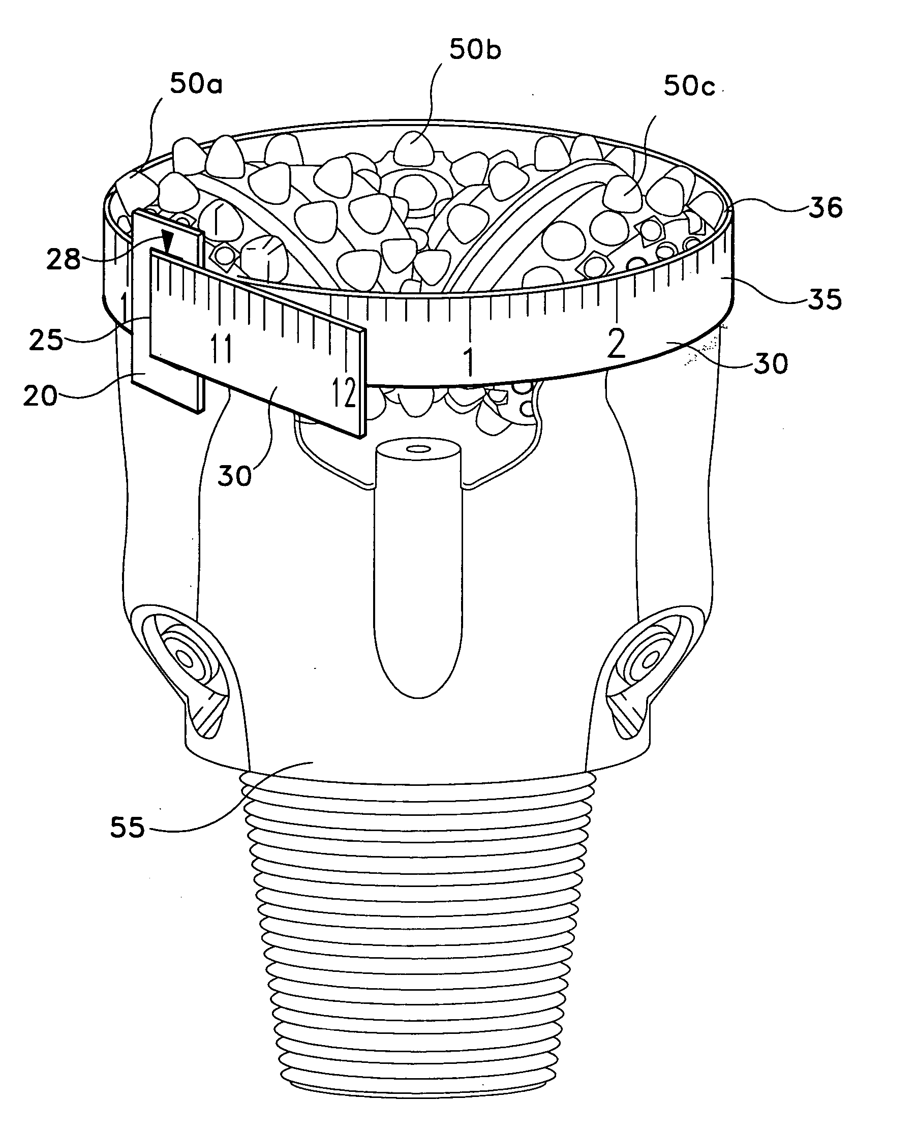
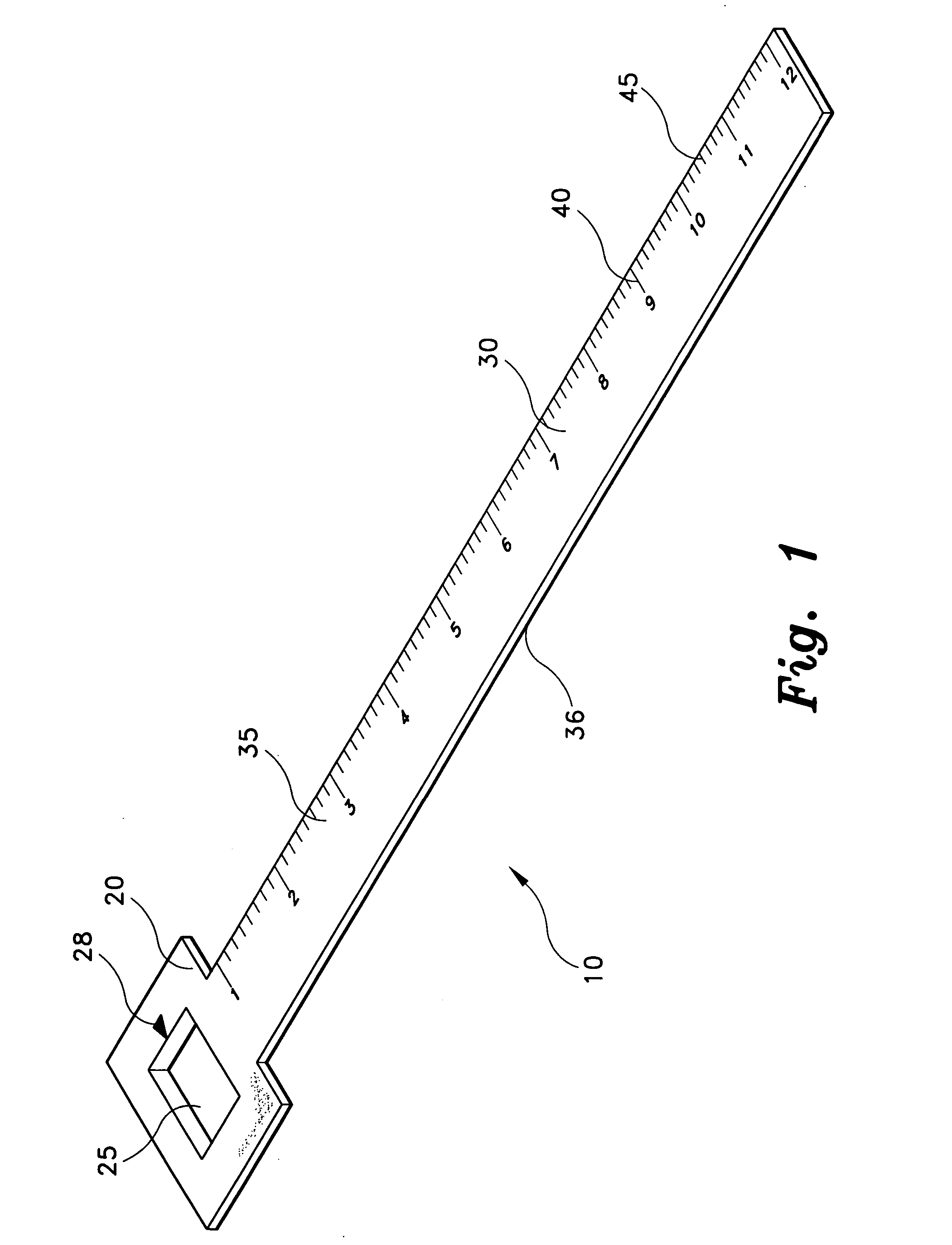
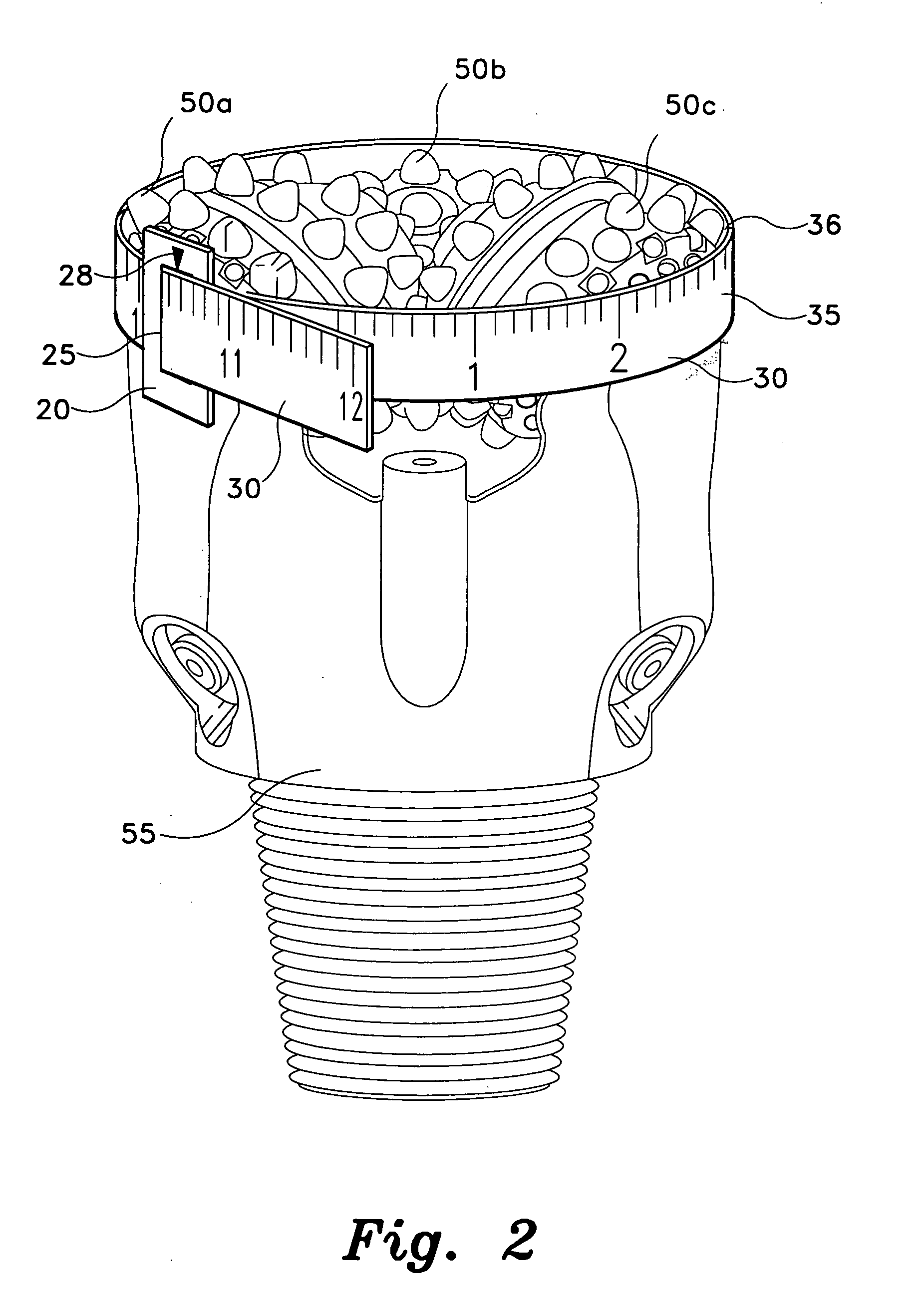
[0030] The present invention is a drill bit and stabilizer gauge, designated generally as 10 in the drawings. The gauge 10 of the present invention is generally designed for use in determining the diameters of drill bits, drill bit stabilizers, and other cylindrical objects having irregular surfaces, although the gauge 10 may also be used for measuring the diameter of cylindrical objects having smooth surfaces.

[0031] Referring to FIG. 1, the gauge 10 is an elongate strip 30 having a substantially rectangular tab 20 on one end. The tab 20 has a substantially rectangular slot 25 defined in the center of the tab. An arrowhead defines a zero marker 28 imprinted on the upper surface 35 of the tab 20 located at, and pointed towards, the midpoint of the slot 25 on at least one side of the tab 20. The elongate strip 30 extends from the base of the tab 20 to a length dictated by the range of diameters to be measured. The elongate strip member 30 is characterized by an upper surface 35 and a...


PUM


Abstract

The drill bit and stabilizer gauge is a flexible, elongate strip that is wrapped about the circumference of a drill bit or drill bit stabilizer to measure the diameter. The strip has a rectangular tab at one end with a slot defined therein so that the opposite end of the strip can be inserted through the slot after being wrapped around the drill bit or stabilizer. A zero pointer is stamped on the tab adjacent the slot to ensure accurate measurement. A scale is imprinted on the strip with markings at each interval of π times the dimensional unit and fractions thereof for reading the diameter directly. The gauge is made from spring steel, a thermoplastic material, or other suitable, inextensible, flexible material which has sufficient elasticity, but also sufficient stiffness, that the strip may be bent into a loop retaining a nearly perfect circular form.

Description

CROSS-REFERENCE TO RELATED APPLICATION [0001] This application claims the benefit of U.S. Provisional Patent Application Ser. No. 60 / 507,960, filed Oct. 3, 2003.BACKGROUND OF THE INVENTION [0002] 1. Field of the Invention [0003] The present invention relates generally to measuring devices. More specifically, the invention is a gauge used to measure the diameter of drill bits and drill bit stabilizers for oil drilling rigs, or more generally, any object with a generally cylindrical shape having an irregular surface. [0004] 2. Description of the Related Art [0005] Many industrial and commercial applications make use of diameter readings for a wide variety of objects. Oilfield drilling is one such industrial application where measuring the diameter of drill bits and drill stabilizers plays a pivotal role and proves troublesome with conventional gauges. A drill bit used in oil well drilling can be of two basic types: a roller cone bit or a fixed body bit. Although both bits drill circul...

Claims


Application Information

Patent Timeline
Patent Type & Authority Applications(United States)
IPC IPC(8): E21B12/00G01B3/10G01B5/02
CPCE21B12/00G01B5/025G01B3/1002G01B3/1004
Inventor SAUNDERS, ERIC W.
Owner SAUNDERS ERIC W
Why Eureka
Try Eureka