Gas directing system and method

Active Publication Date: 2005-04-07
NOW LEO
View PDF5 Cites 4 Cited by
  • Summary
  • Abstract
  • Description
  • Claims
  • Application Information

AI Technical Summary

Benefits of technology

[0007] In accordance with yet another aspect of the invention, a method for increasing horsepower in an internal combustion engine is provided. In accordance with the method, a gas directing mechanism is attached to the internal combustion engine and the velocity of the air flowing out of the gas directing mechanism is increased in order to i

Problems solved by technology

The difference between the first characteristic and the second characteri

Method used


Image

  • Gas directing system and method
  • Gas directing system and method
  • Gas directing system and method

Examples


Example

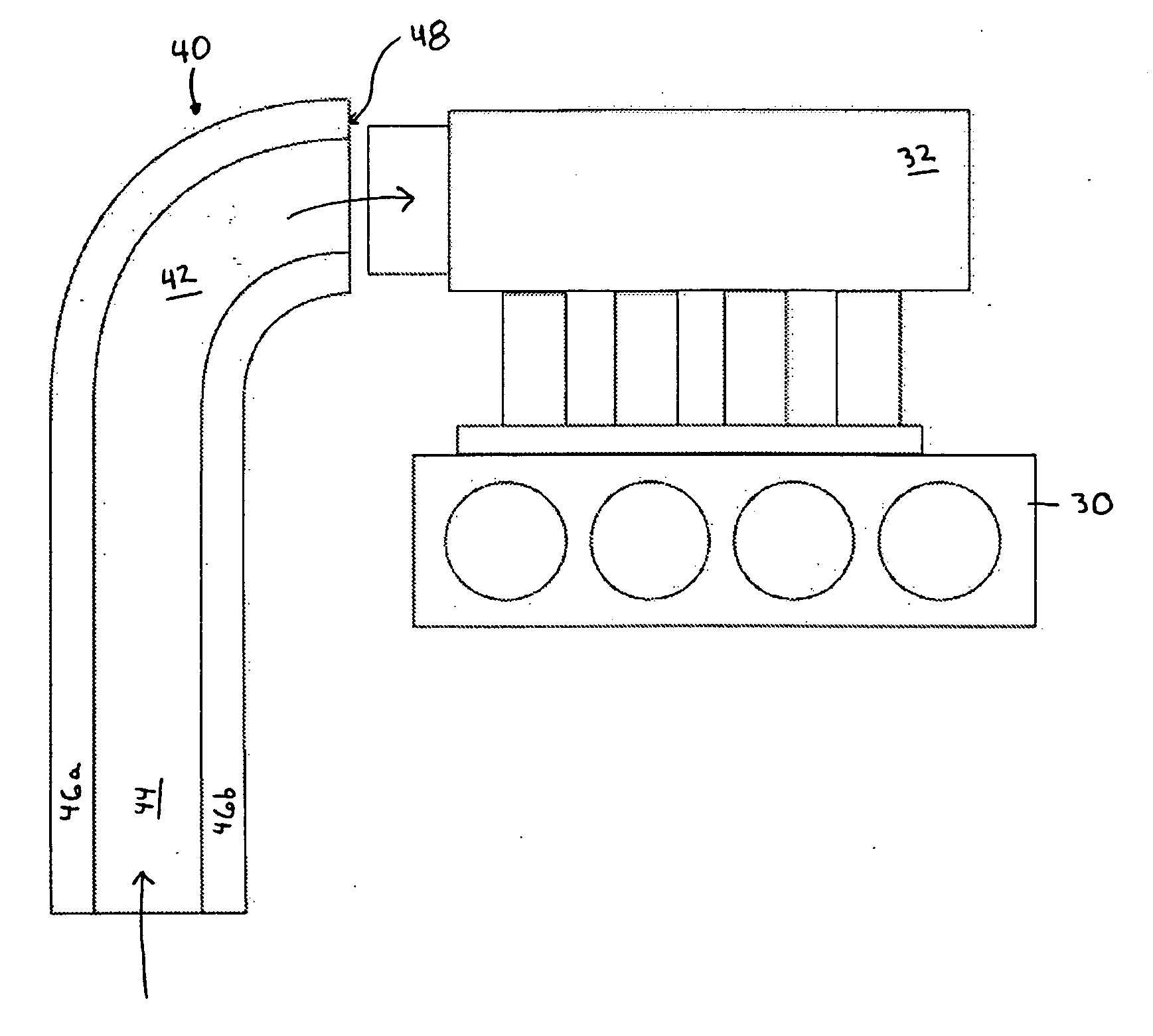
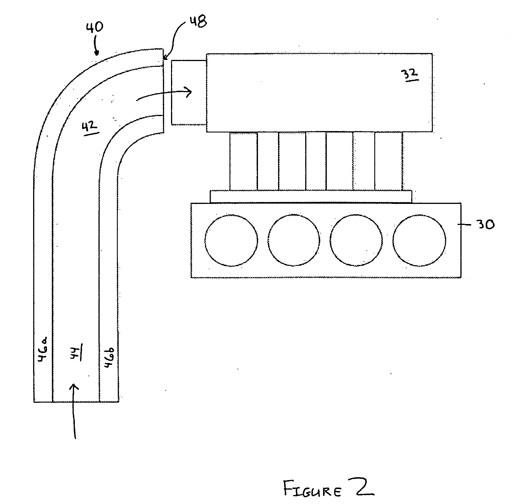
[0019] The invention is particularly applicable to an gas directing system for an internal combustion engine, such as a vehicle engine, and it is in this context that the invention will be described. It will be appreciated, however, that the gas directing system and method in accordance with the invention has greater utility since it may be used to direct various different gases including air and may be used with various types of internal combustion engines that are used for various different purposes. The gas directing system may also be used with any system in which it is desirable to provide increased gas flow.

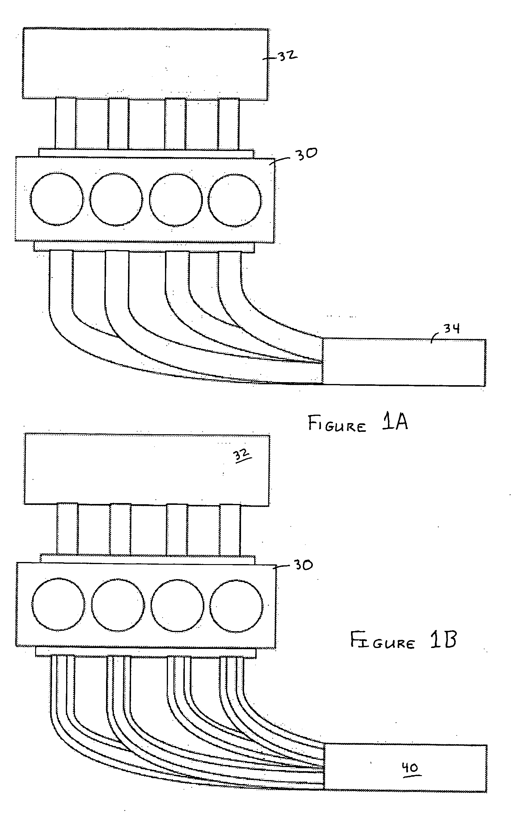
[0020]FIGS. 1A and 1B are diagrams illustrating a typical exhaust manifold for an internal combustion engine and an exhaust manifold in accordance with the invention, respectively. In particular, FIG. 1 illustrates a typical internal combustion engine 30 with a typical gas directing manifold 32 and a typical exhaust manifold 34 as are well known. The gas directing manifold...


PUM


Abstract

An gas directing/exhaust system and method are provided. The gas directing system has an gas directing mechanism. The gas directing mechanism has different embodiments. In some embodiments, the gas directing mechanism has a first pathway and a second pathway. In other embodiments, the gas directing mechanism has a second pathway and one or more first pathways located inside of the second pathway. In other embodiments, the gas directing mechanism has the first and second pathways and a third pathway inside of the second pathway.

Description

FIELD OF THE INVENTION [0001] The invention relates generally to a system and method for directing a gas flow and in particular to a system and method for directing gases (intake gas or exhaust gases) in an internal combustion engine. BACKGROUND OF THE INVENTION [0002] It is well known that internal combustion engines require a flow of air to operate. In particular, the air and fuel are mixed together and then ignited to generate energy which translates into power, for example, to move a piston up. An internal combustion engine may be used for a variety of different purposes, including powering a vehicle, generating energy, such as a gasoline powered portable generator, and many other uses. The temperature and amount of air flowing into the internal combustion engine affects the performance of the engine as is well known. [0003] In order to increase the performance of an internal combustion engine, the temperature and amount of air being provided to the internal combustion engine ma...

Claims


Application Information

Patent Timeline
IPC IPC(8): F01N13/08F01N13/10F01N13/16F02B27/02F02M35/10F02M35/108
CPCF01N13/082F02B27/04F01N13/16F02M35/10098F02M35/10118F02M35/10124F02M35/10144F02M35/10222F02M35/10327F02M35/1036F02M35/1038F02M35/108F02M35/112Y02T10/146F02B27/005F01N13/10Y02T10/12
Inventor NOW, LEO
Owner NOW LEO
Why Eureka
Try Eureka