Liquid crystal display device

a liquid crystal display and display device technology, applied in lighting device details, instruments, lighting and heating apparatus, etc., can solve the problems of increasing power consumption, large increasing size of portable phones, so as to increase the portability of electronic equipment, reduce power consumption of electronic equipment, and increase the utilization ratio of light

Inactive Publication Date: 2005-04-07
CITIZEN WATCH CO LTD
View PDF3 Cites 94 Cited by
  • Summary
  • Abstract
  • Description
  • Claims
  • Application Information

AI Technical Summary

Benefits of technology

[0014] The present invention has been conceived to solve the above-described problems and an aspect of the invention is to thin a liquid crystal display device, which is capable of displaying images on both sides, and increase the portability of electronic equipments that incorporate therein the display device, and further, increase the utilization ratio of light from a backlight to allow reduction in power consumption of the electronic equipments.

Problems solved by technology

Additionally, as information communication using, for example e-mail, makes progress, a liquid crystal display screen also becomes large in size and accordingly, a portable phone becomes large in size.
However, a problem arises in that two liquid crystal display devices are incorporated in the above-described conventional portable phone, causing increase in power consumption.
Additionally, since the portable phone is configured to dispose two liquid crystal display devices so that the rear surfaces of the display devices face each other, the thickness of the display unit is increased, disadvantageously decreasing portability of the phone.
Additionally, when other necessary components such as a support frame are mounted to those display devices, the portable phone becomes very thick.
As described above, the conventional liquid crystal display device capable of displaying images on both sides includes some problems.
That is, 50% or more of light from the backlight is consumed away and therefore, the portable phone disadvantageously dissipates twice the power as a portable phone with a single display, and further, the display unit of electronic equipments incorporating therein such conventional liquid crystal display device becomes thick, decreasing the portability of electronic equipments.

Method used


Image

  • Liquid crystal display device
  • Liquid crystal display device
  • Liquid crystal display device

Examples


first embodiment

O 4

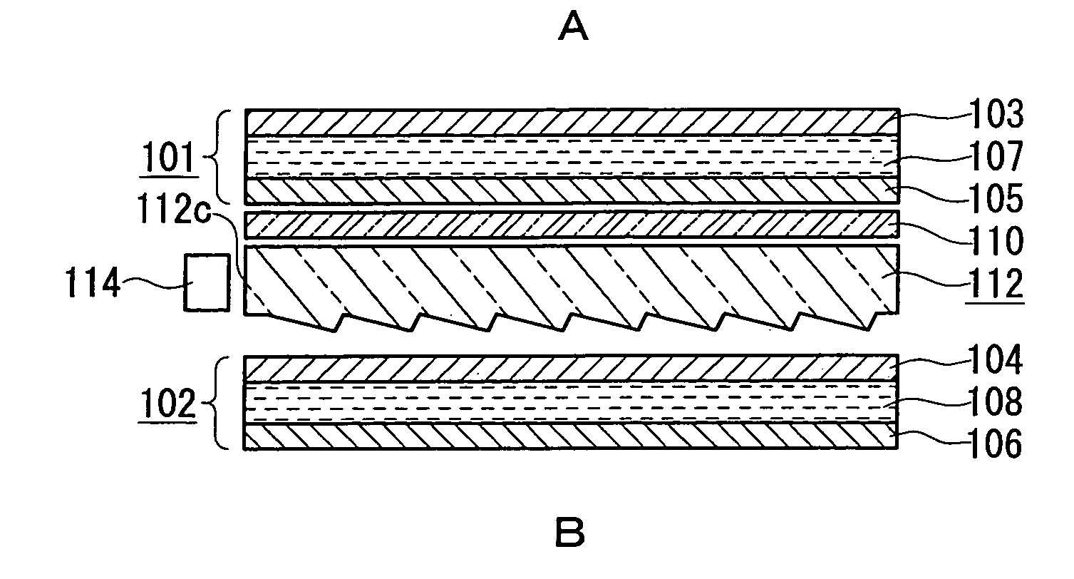
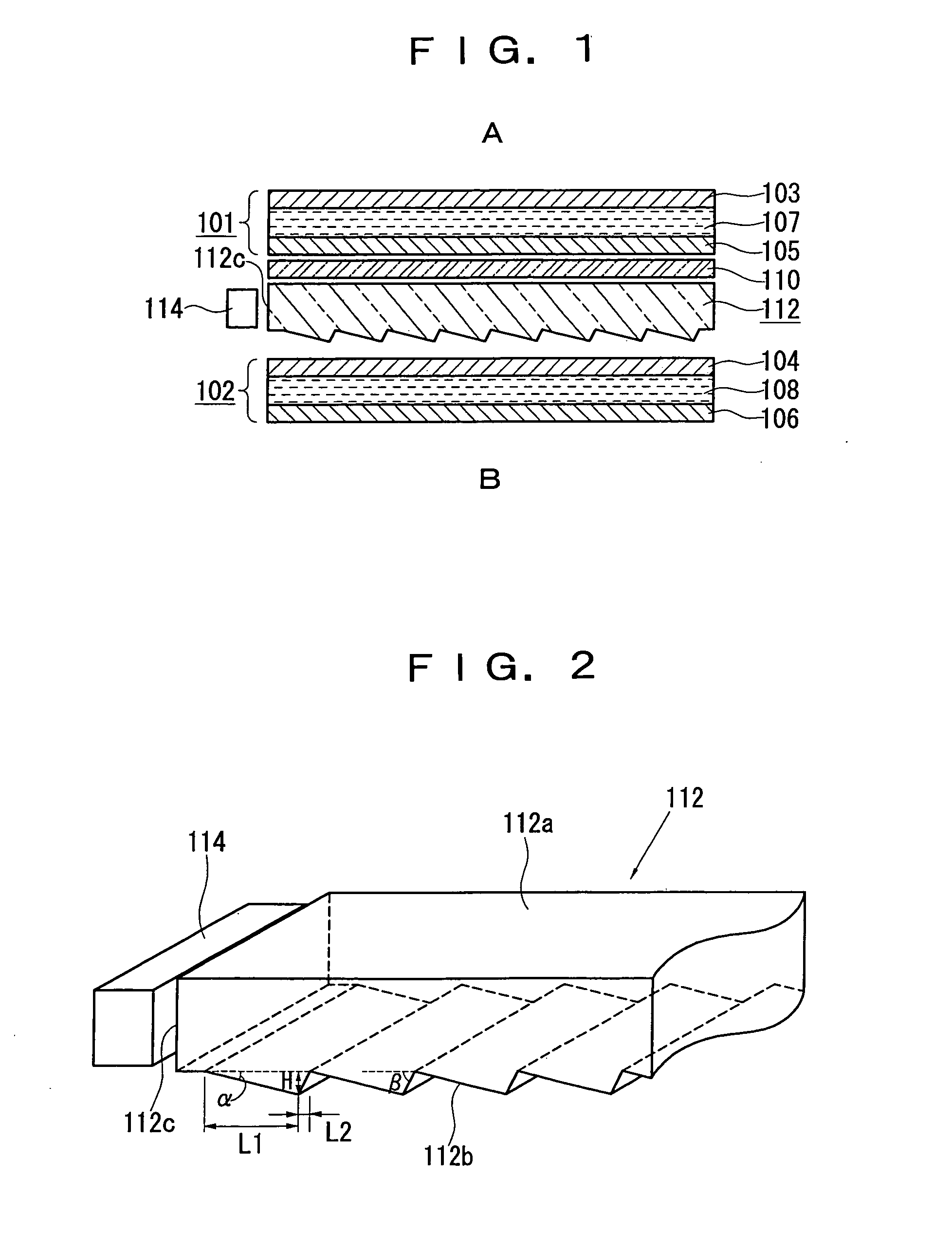
[0040]FIG. 1 is a schematic cross sectional view illustrating a first embodiment of a liquid crystal display device according to the invention.

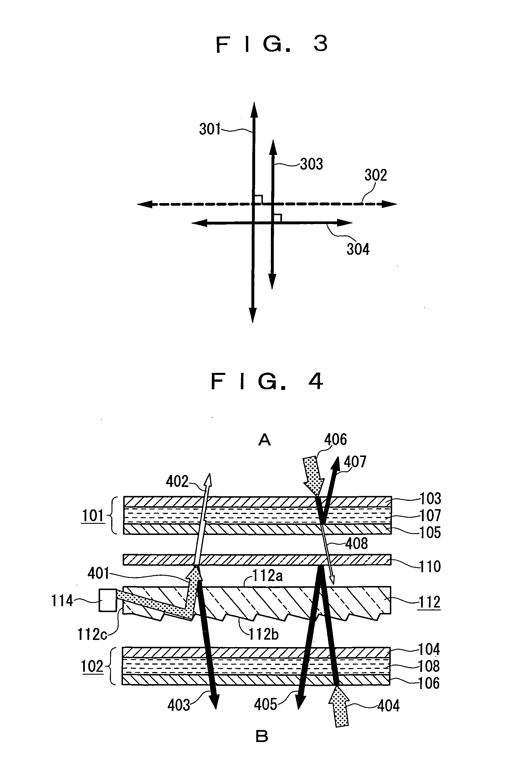
[0041] The liquid crystal display device shown in FIG. 1 has a first liquid crystal panel 101, polarization separator 110, light guide plate 112, and a second liquid crystal panel 102 arranged in this order from top to bottom in the figure. Accordingly, in this embodiment, the polarization separator 110 is provided only between the first liquid crystal panel 101 and the light guide plate 112, and no component is provided between the second liquid crystal panel 102 and the light guide plate 112.

[0042] The first liquid crystal panel 101 includes a first liquid crystal cell 107 having a liquid crystal layer sandwiched between two glass substrates, a first polarizer 103 disposed on a viewing side “A”, and a second polarizer 105 disposed on a side opposite the viewing side “A”. Furthermore, though not shown, the first liquid crystal cell 107 ...

second embodiment

D 6

[0070] Thereafter, a second embodiment of the liquid crystal display device according to the invention will be explained. FIG. 5 is a schematic cross sectional view of the liquid crystal display device and FIG. 6 is a schematic cross sectional view to explain how the liquid crystal display device performs a display function.

[0071] The second embodiment is different from the first embodiment in that a transflective reflector 120 is disposed between a light guide plate 112 and a liquid crystal panel 102, and a transflective layer is not provided within a first liquid crystal panel 502. The configuration other than the above-mentioned configuration and display theory are approximately the same as those explained in the description of the first embodiment. The second embodiment will be explained in detail below.

[0072] Referring to FIG. 5, the transflective reflector 120 is disposed between the light guide plate 112 and the second liquid crystal panel 102. The transflective reflecto...

third embodiment

ND 8

[0090] Thereafter, a third embodiment of the liquid crystal display device according to the invention will be explained. FIG. 7 is a side view of a light guide plate and light source of the liquid crystal display device, and FIG. 8 is a schematic cross sectional view to explain how the liquid crystal display device performs a display function.

[0091] The third embodiment is different from the above-described second embodiment only in the configuration of a light guide plate. In the first and second embodiments, a light guide plate including prisms arranged on one surface of an acrylic plate to have a height of several micrometers and a constant pitch has been used. Such a light guide plate generally needs to be manufactured with high processing accuracy. In the third embodiment, a light guide plate that is generally said to allow facilitated manufacture, increase in yield and simplified processing is employed.

[0092] As shown in FIG. 7, a light guide plate 801 is made of acrylic...


PUM

PropertyMeasurementUnit
thicknessaaaaaaaaaa
thicknessaaaaaaaaaa
thicknessaaaaaaaaaa

Abstract

A liquid crystal display device has first and second liquid crystal panels (101, 102) mainly comprising liquid crystal cells (107, 108), respectively, disposed back to back to enable the visual recognition of the liquid crystal panels (101, 102). A light guide plate (112) is disposed between the first liquid crystal panel (101) and the second liquid crystal panel (102) with a light source (114) located adjacent to its one end face (112c), and a polarization separator (110) located between the first liquid crystal panel (101) and the light guide plate (112). Light emitted from the light guide plate (112) is split into two beams of polarized light: one is emitted to the first liquid crystal panel (101), and the other to the second liquid crystal panel (102) through the light guide plate (112). This constitution thins down a both-sided display liquid crystal display device and reduces power consumption.

Description

TECHNICAL FIELD [0001] The present invention relates to a liquid crystal display device, and particularly to a liquid crystal display device for both-sided display, having two liquid crystal panels disposed back to back to enable the visual recognition of the liquid crystal panels. BACKGROUND TECHNOLOGY [0002] A liquid crystal display device has made rapid progress as a low power, thin and light-weighed display device in various fields. Particularly in recent years, a portable phone (cellular phone) also has made drastic progress and all types of portable phones employ the liquid crystal display device. [0003] The liquid crystal display device employed in the portable phone is in many cases a reflective liquid crystal display device that is designed especially from the view point of low power consumption so that the life time of a battery is elongated. Furthermore, almost all of the reflective liquid crystal display devices are a transflective liquid crystal display device incorpora...

Claims


Application Information

Patent Timeline
Patent Type & Authority Applications(United States)
IPC IPC(8): G02F1/13357
CPCG02F1/133615G02F2001/133342G02F1/13362G02F1/133342
Inventor AKIYAMA, TAKASHI
Owner CITIZEN WATCH CO LTD
Why Eureka
Try Eureka