

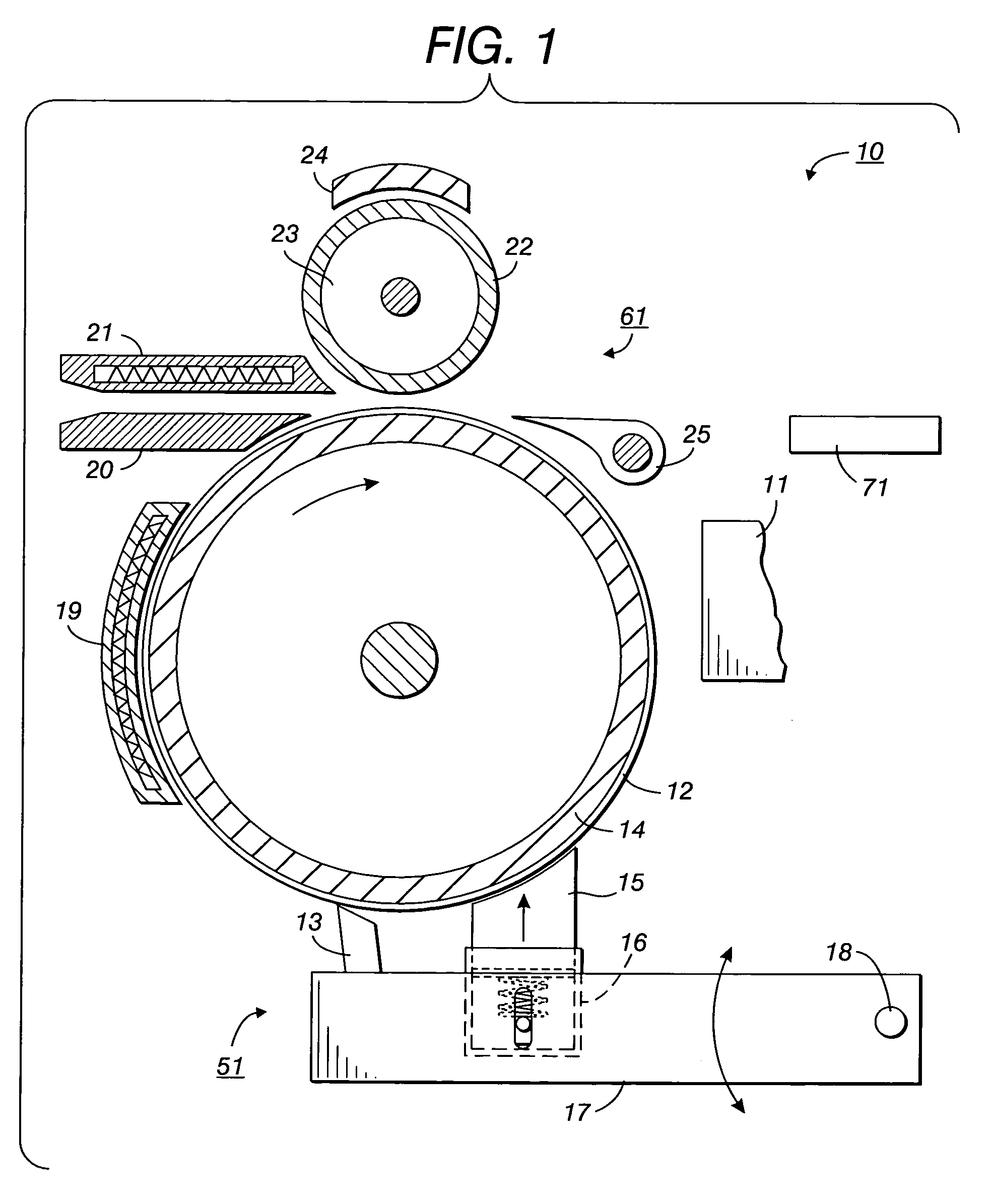
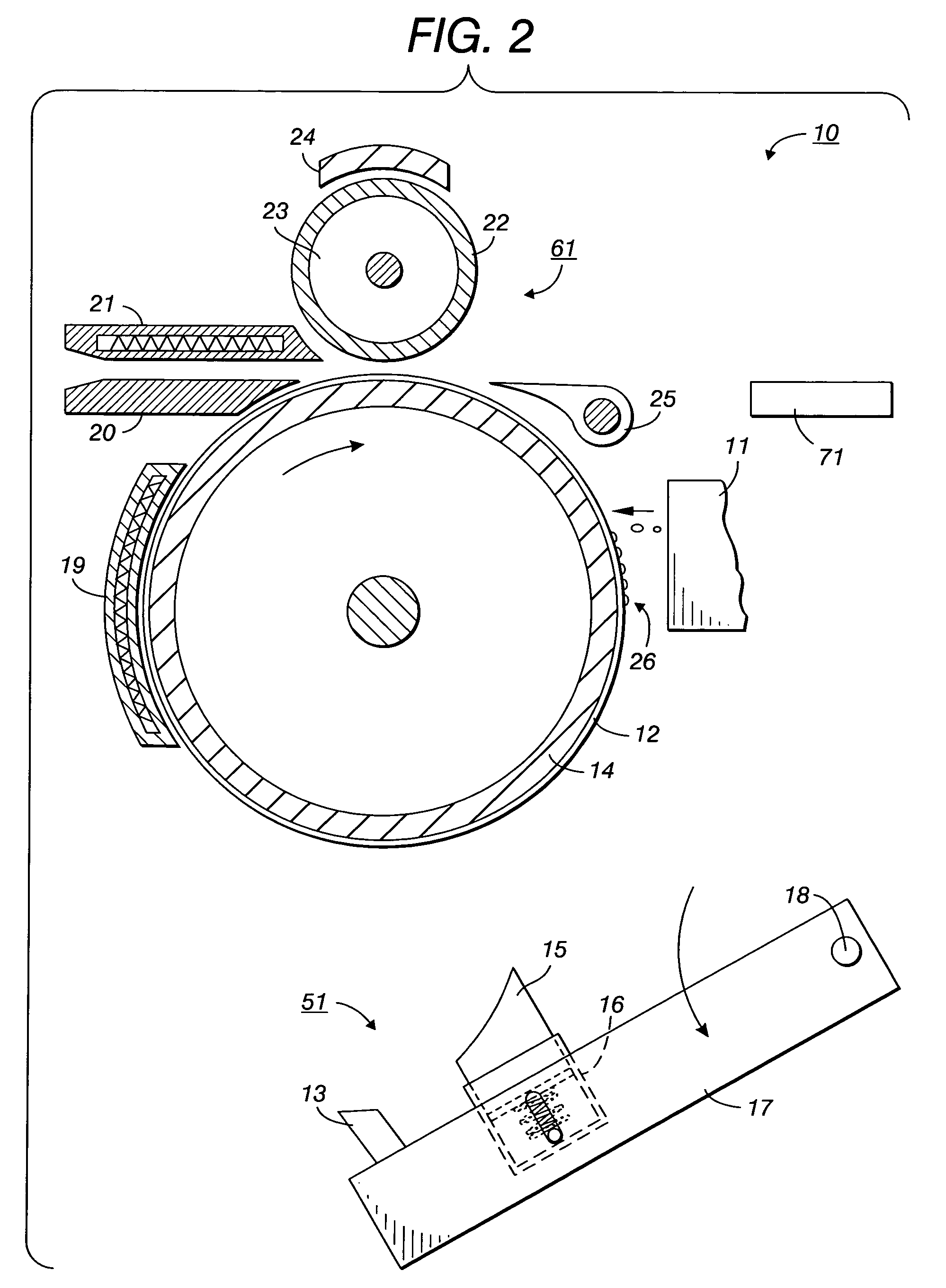
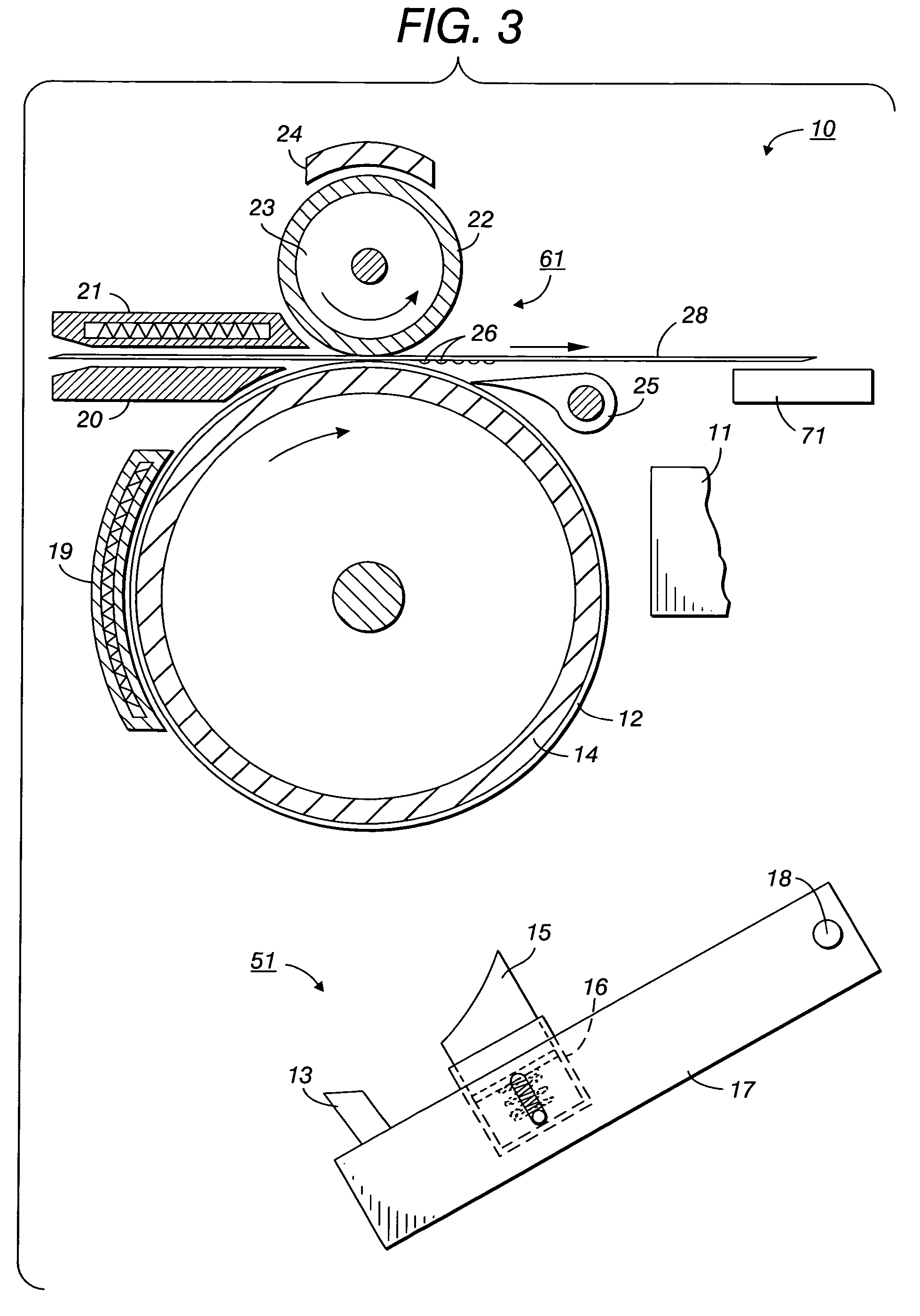
Printing apparatus and processes employing intermediate transfer with molten intermediate transfer materials
a technology of intermediate transfer and printing apparatus, which is applied in the direction of electrographic process apparatus, printing, instruments, etc., can solve the problems of inability to allow oil to pass through the maintenance cartridge and affecting the quality of the intermediate transfer member
- Summary
- Abstract
- Description
- Claims
- Application Information
AI Technical Summary
Benefits of technology
Problems solved by technology
Method used
Image

Examples
example i
To a 4-neck, round bottom flask equipped with a stirrer, condenser, temperature controller, and sparge tube are charged 200 grams of 1-octadecene (available from CPChem Company, The Woodlands, Tex.), 100 grams of toluene, and 52.8 grams of polymethylhydrosilane HMS-991 (available from Gelest, Inc., Tullytown, Pa.) of the following formula:
(n=22-30, MW=1,500-1,900 g / mol). The flask contents are agitated and heated to 100° C. The reaction mixture is sparged with a light stream of nitrogen gas. After equilibrating at the mentioned temperature, heating and sparging are discontinued, and the reaction is catalyzed with 0.3 cc of 3.3% chloroplatinic acid solution in ethanol. Subsequently, the temperature of the reaction mixture goes to a maximum of 110° C. within 10 minutes. After the reaction goes to completion, the mixture is treated with 2% water and 0.2% concentrated HCl at a temperature of approximately 60° C. for one hour. Afterwards, the reaction mixture is neutralized with dry ...
example ii
To a 4-neck, round bottom flask equipped with a stirrer, condenser, temperature controller, and sparge tube are charged 200 grams of allyl alcohol propoxylate (available from Aldrich Chemical Co., Milwaukee, Wis., Cat. Number 43,037-4), of the formula
wherein x represents the number of repeat propoxylate groups (average value of from about 1.4 to about 1.8; average number average molecular weight 140-160), 90 grams of toluene, and 283.8 grams of methylhydrosiloxane dimethylsiloxane Copolymer HMS-301 (available from Gelest, Inc., Tullytown, Pa.) of the following formula:
(m=7-9, n=17-19, MW=1,900-2,000 g / mol). The flask contents are agitated and heated to 95° C. with a light nitrogen sparge. After equilibrating at this temperature, heating and sparging are discontinued, and the reaction is catalyzed with 0.3 cc of 3.3% chloroplatinic acid solution in ethanol. Subsequently, the temperature of the reaction mixture goes to a maximum of 110° C. within 10 minutes. After the reaction ...
example iii
To a 4-neck, round bottom flask equipped with a stirrer, condenser, temperature controller, and sparge tube are charged 300 grams of the product prepared in Example II and 310 grams of stearyl isocyanate (available as Mondur O from Bayer Corp., Pittsburgh, Pa.). The mixture is melted in the flask, brought to a temperature of 120° C., and stirred. After thermal equilibrium has been reached, 2 drops of a catalyst solution (dibutyltin oxide, FASCAT® 4202, available from Atofina Chemicals, Philadelphia, Pa.) are added. The reaction becomes exothermic, and the temperature peaks at 150° C. Subsequently, the reaction mixture is stirred for another 1.5 hours. FTIR analysis can be used to determine that all of the isocyanate has reacted with the alcohol groups of the dimethicone copolyol from Example II. It is believed that the product obtained will have the formula
wherein m=7-9, n=17-19, and x has an average value of from about 1.4 to about 1.8.
PUM
 Abstract
Description
Claims
Application Information