Wireless microphone

Inactive Publication Date: 2005-04-07
PHONAK COMM
View PDF36 Cites 41 Cited by
  • Summary
  • Abstract
  • Description
  • Claims
  • Application Information

AI Technical Summary

Benefits of technology

[0004] According to the present invention, the above-mentioned objects are achieved in particular in that a wireless microphone comprising a radio transmitter for transmitting radio signals carrying audio signals to a hearing device is provided with at least one coupling element for detachably fixing one of various interchangeable functional modules to the wireless microphone, said coupling element comprising electrical contacts for electrically connecting the interchangeable functional module to the wireless microphone when the interchangeable functional module is fixed to the wireless microphone by means of said coupling element. As the coupling element makes it possible to fix and connect different functional modules to the wireless microphone, the wireless microphone can be limited to an assistive listening device with basic functions and features, extendible by the user with extra functions and features as needed. The user can easily adapt the functionality of the assistive listening device to the requirements of a new situation by fixing (and thereby connecting) a desired functional module to the wireless microphone. The wireless microphone and an additional functional module fixed and connected thereto can be carried comfortably by the user as one unit.
[0005] In a preferred embodiment, the coupling element constitutes a bidirectional electri

Problems solved by technology

However, the users often find the connective wires not very practical.
Because the wireless microphone needs to be placed at wire's length from the audio source, the wireless microphone is not always within reach of the user.
Although these additional features are not used all

Method used


Image

  • Wireless microphone
  • Wireless microphone

Examples


Example

[0016] In the following description the term audio signal refers to acoustic signals audible to humans, typically in the range of 100 Hz to 8 KHz or, in the case of high fidelity electronic devices, in the extended range of 20 Hz to 20 KHz. The term electrical audio signal refers to electrical signals representing audio signals in analogue or encoded form.

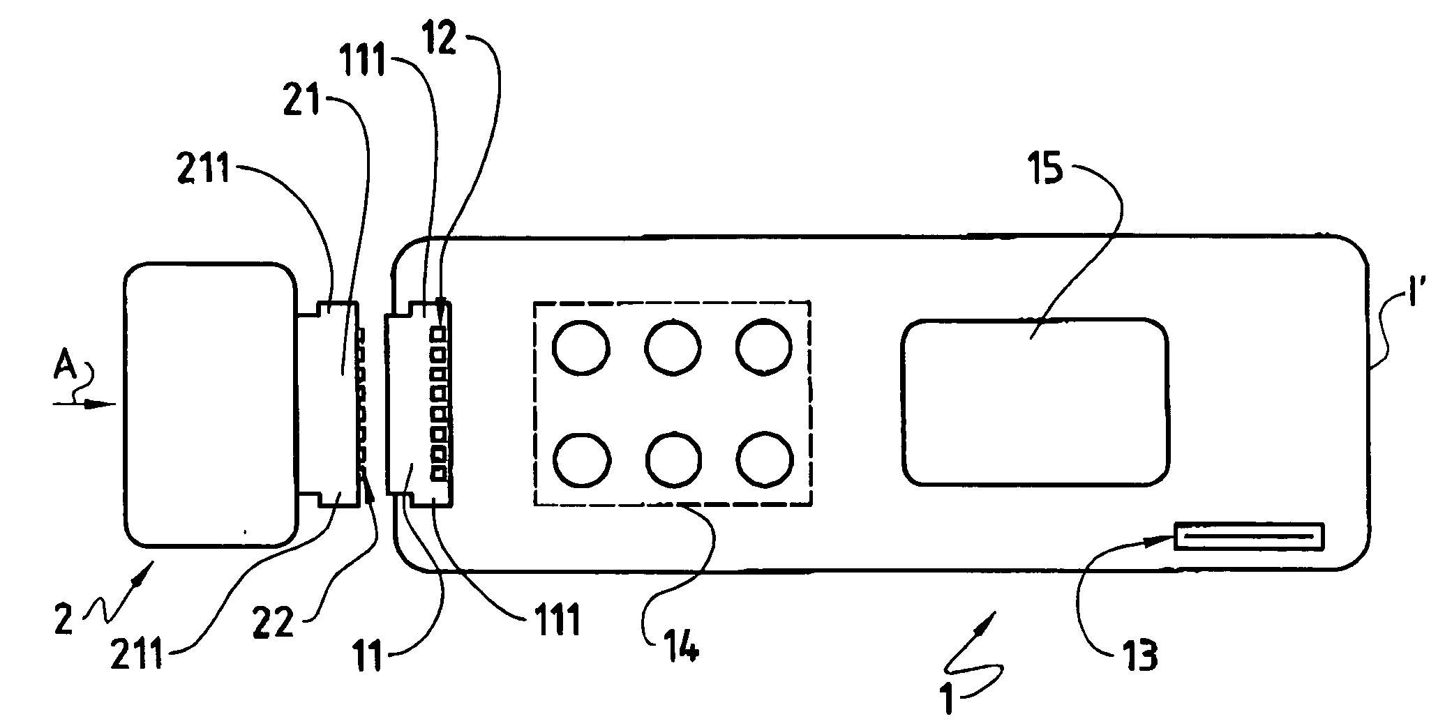
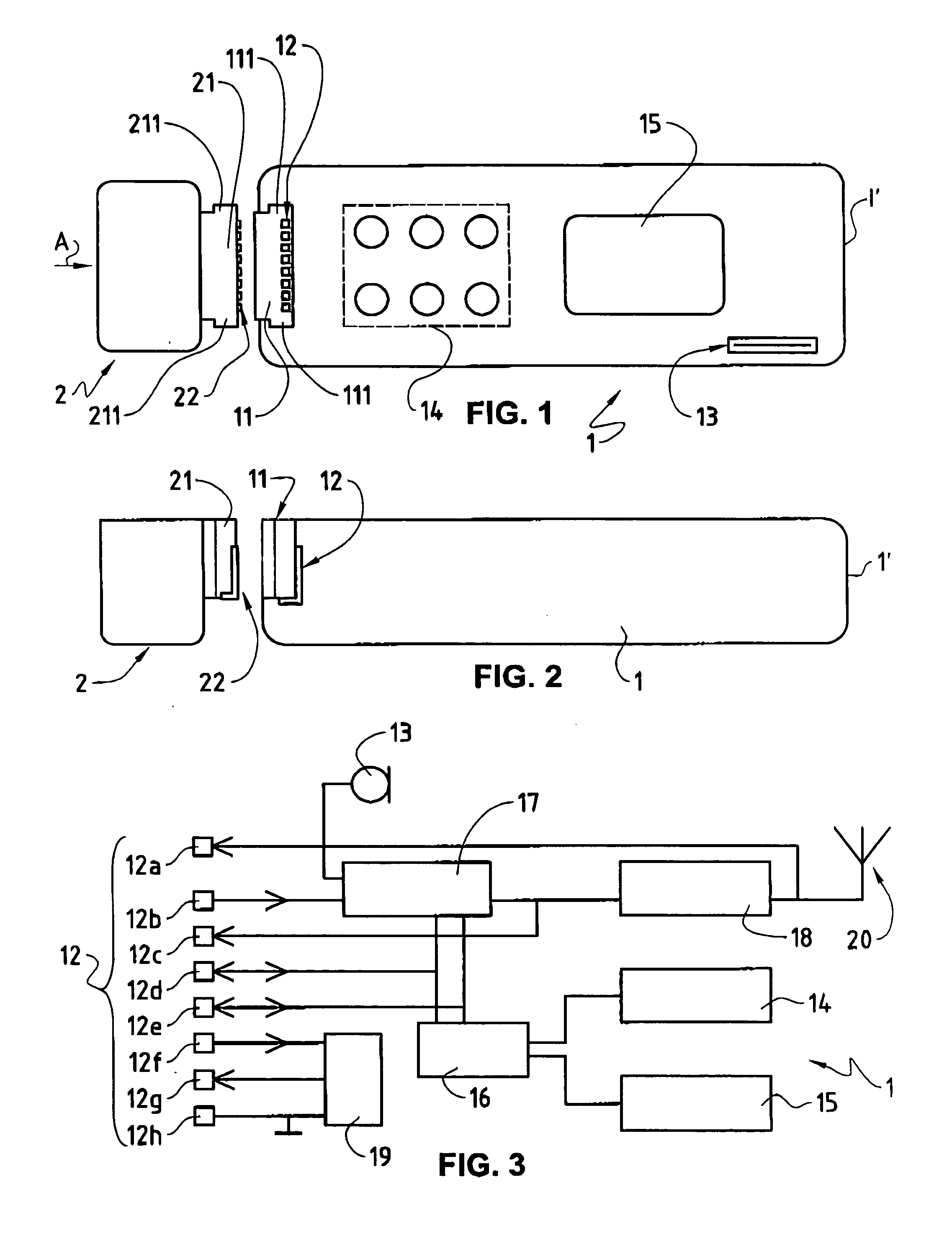
[0017] In the FIGS. 1, 2 and 3, the reference numeral 1 refers to a wireless microphone having a housing 1′ and a microphone element 13 for receiving audio signals from sound sources. As can be seen in FIGS. 1 and 3, the wireless microphone 1 also includes user interface comprising operating elements 14, such as push buttons, and a display 15.

[0018] As is illustrated in FIGS. 1 and 2, the wireless microphone 1 comprises a coupling element 11 for detachably fixing an interchangeable functional module 2 to the wireless microphone 1. The coupling element 11 is designed to fix the interchangeable functional module 2 to the wireless m...


PUM


Abstract

A wireless microphone (1) comprises a radio transmitter for transmitting radio signals carrying audio signals to a hearing device. The wireless microphone (1) further comprises at least one coupling element (11) for detachably fixing one of various interchangeable functional modules (2) to the wireless microphone (1). The coupling element (11) is designed to fix the interchangeable functional module (2) to the wireless microphone (1) by mating with a coupling element (21) of the interchangeable functional module (2). The coupling elements (11, 21) comprise electrical contacts (12, 22) for electrically connecting the interchangeable functional module (2) to the wireless microphone (1) when the interchangeable functional module (2) is fixed to the wireless microphone (1) by means of said coupling elements (11, 21). The coupling element (11) constitutes a bidirectional electrical interface between the wireless microphone (1) and the interchangeable functional module (2). The wireless microphone (1) can be limited to an assistive listening device with basic functions and features, extendible by the user with extra functions and features as needed.

Description

BACKGROUND OF THE INVENTION [0001] The present invention relates to a wireless microphone; specifically, the present invention relates to a wireless microphone comprising a radio transmitter for transmitting radio signals carrying audio signals to a hearing device. [0002] Wireless microphones are used as assistive listening devices for transmitting sound from the sound source directly to a hearing device arranged in or at a person's ear, whereby the signal-to-noise ratio is greatly improved. The wireless microphones currently available for that purpose comprise radio transmitters for transmitting radio signals that carry audio signals to a radio receiver of a hearing aid, for example a behind-the-ear (BTE) hearing instrument, or to a radio receiver with an electro-acoustic converter reproducing the sound directly into the ear. Common applications of wireless microphones as assistive listening devices include applications in schools, where the teacher wears the wireless microphone an...

Claims


Application Information

Patent Timeline
IPC IPC(8): H04M1/00H04R25/00
CPCH04R25/554H04R2225/021H04R25/558
Inventor GERBER, LOUISGYSIN, STEFAN
Owner PHONAK COMM
Why Eureka
Try Eureka