Cleaning pad and cleaning implement

a technology of cleaning implements and cleaning pads, which is applied in the direction of carpet cleaners, cleaning equipment, cleaning machines, etc., can solve the problems of requiring the inconvenience of performing one or more cleaning steps, affecting the cleaning effect, and requiring significant soil redeposition, so as to reduce the effect of drippag

a technology of cleaning implements and cleaning pads, which is applied in the direction of carpet cleaners, cleaning equipment, cleaning machines, etc., can solve the problems of requiring the inconvenience of performing one or more cleaning steps, affecting the cleaning effect, and requiring significant soil redeposition, so as to reduce the effect of drippag

US20050076936A1Inactive Publication Date: 2005-04-14THE PROCTER & GAMBLE COMPANY

Image

  • Cleaning pad and cleaning implement
  • Cleaning pad and cleaning implement
  • Cleaning pad and cleaning implement

Examples


example

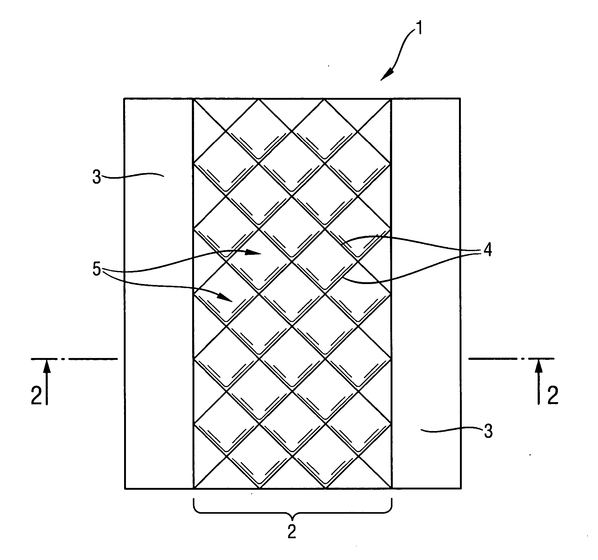
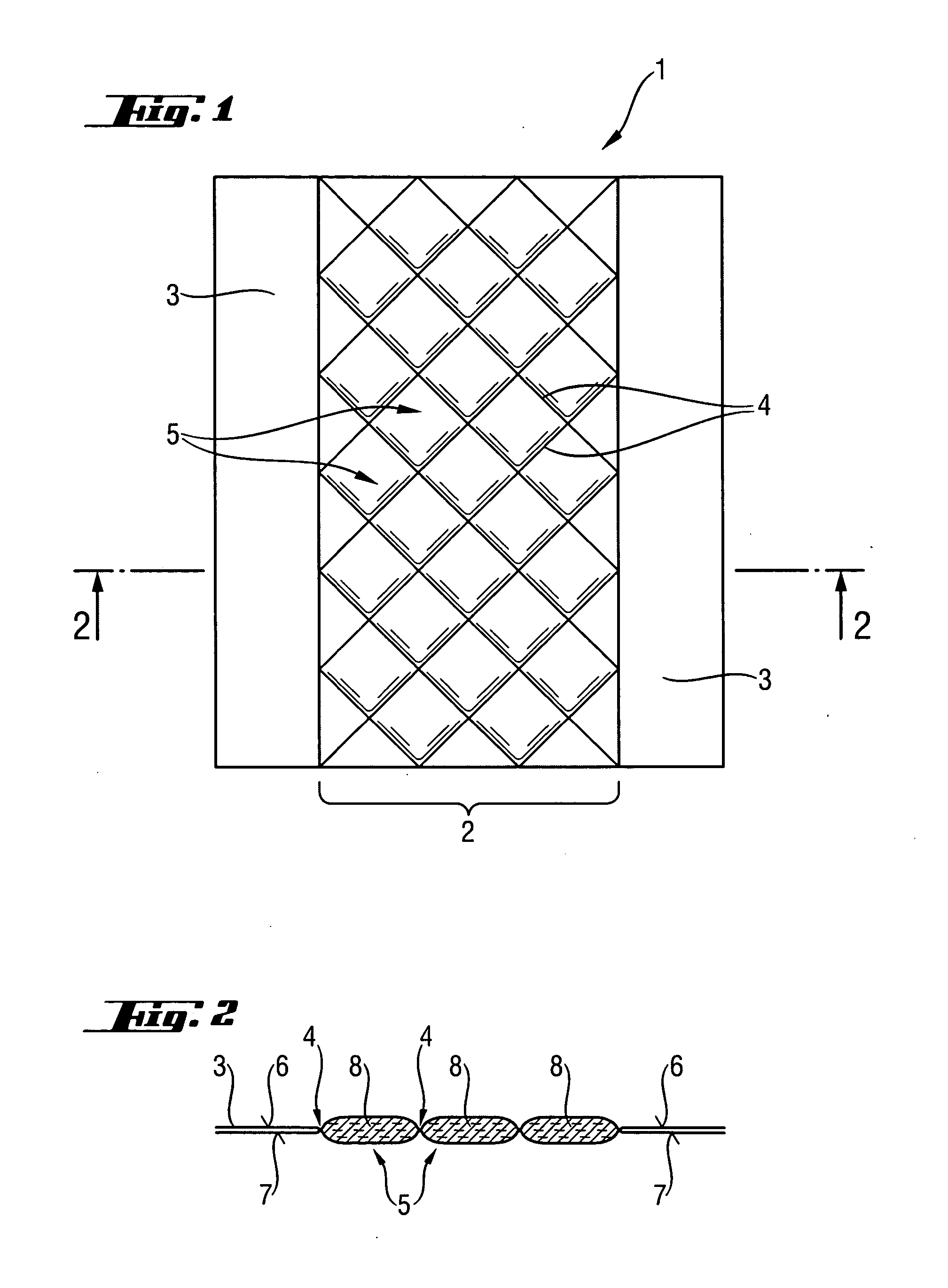
Two dry Swiffer Wet® pads were bonded throughout their thickness, one pad to comprise a plurality of adjacent diamond-shaped reservoirs (as shown in FIG. 1), and the other pad to have a wave pattern extending along the length of the pad, and which does not define discrete fluid reservoirs. (The wave pattern applied was obtained by scanning a Pledge Grab-It Wet pad). The pads were bonded by the following ultrasonic method:

Equipment Used

1. Branson Ultrasonic unit Model 900 BCA 2. 9″ Carbide Horn 3. Magnesium Photo engraved patterned plate 4. Woven Teflon

Process Conditions 1. Amplitude is set to >50% 2. Horn pressure is 30 psig 3. Speed on this particular unit is set to 4 on the dial. This gauge does not give a specified fpm. 4. The gap between the pattern and the horn is set to zero. A piece of woven Teflon material is placed between the horn and the pattern to provide less friction between the two as the pattern moves past the horn.

Steps to Make an Ultrasonically Bond...


PUM

PropertyMeasurementUnit
aspect ratioaaaaaaaaaa
surface areaaaaaaaaaaa
contact angleaaaaaaaaaa

Abstract

The present invention relates to disposable cleaning pads for removable attachment to a cleaning implement, the cleaning pad comprising an absorbent structure, and a plurality of reservoirs defined in the absorbent structure, formed by bonding or embossing throughout the thickness of the absorbent structure.

Description

FIELD OF THE INVENTION The present invention relates to cleaning pads and cleaning implements for cleaning hard surfaces, and in particular floors. More particularly, the present invention relates to pre-moistened cleaning pads. BACKGROUND OF THE INVENTION Numerous implements are known for cleaning hard surfaces such as tiled floors, linoleum floors, hardwood floors, counter tops and the like. In the context of cleaning floors, suitable implements typically comprise a handle and means for applying a liquid cleaning composition. Some implements are reusable, including mops containing cotton strings, cellulose and / or synthetic strips, sponges, and the like. While these mops are successful in removing many soils from hard surfaces, they typically require the inconvenience of performing one or more rinsing steps during use to avoid saturation of the material with dirt, soil, and other residues. This requires the use of a separate container to perform the rinsing step(s), and typically...

Claims


Application Information

Patent Timeline
14 Apr 2005
Publication
US20050076936A1
IPC
A47L13/17; A47L13/20; B32B3/28; B32B7/04
CPC
A47L13/17; B32B7/04; B32B3/28; A47L13/20; B32B2432/00; B32B38/06
Inventors
PUNG, DAVID JOHN; O'DONNELL, HUGH JOSEPH