Post patch assembly for mounting devices in a tire interior

Inactive Publication Date: 2005-04-14
MICHELIN RECH & TECH SA
View PDF3 Cites 193 Cited by
  • Summary
  • Abstract
  • Description
  • Claims
  • Application Information

AI Technical Summary

Benefits of technology

[0015] Another advantage in accordance with certain embodiments of the present technology lies in providing improved technology for mounting a battery used to power tire electronics systems. A significant improvement disclosed by the present technology in light of known designs is that a relatively heavy battery is relocated to the patch-mounting portion of the tire electronics system from its previous position in combination with the electronics portion of the tire electronics system. Such positioning of the battery results in an overall structure with a lower center of gravity than previous tire electronics assemblies, thus having increased mechanical stability and survivability in a tire environment.
[0016] Yet another advantage in accordance with certain embodiments of the presently disclosed technology is that techniques are provided for increasing the transmission range of a data transmitter within the electroni

Problems solved by technology

While various tire monitoring patch and electronics systems have been developed, no one design has emerged that generally addresses all of the ab

Method used


Image

  • Post patch assembly for mounting devices in a tire interior
  • Post patch assembly for mounting devices in a tire interior
  • Post patch assembly for mounting devices in a tire interior

Examples


Embodiment Construction

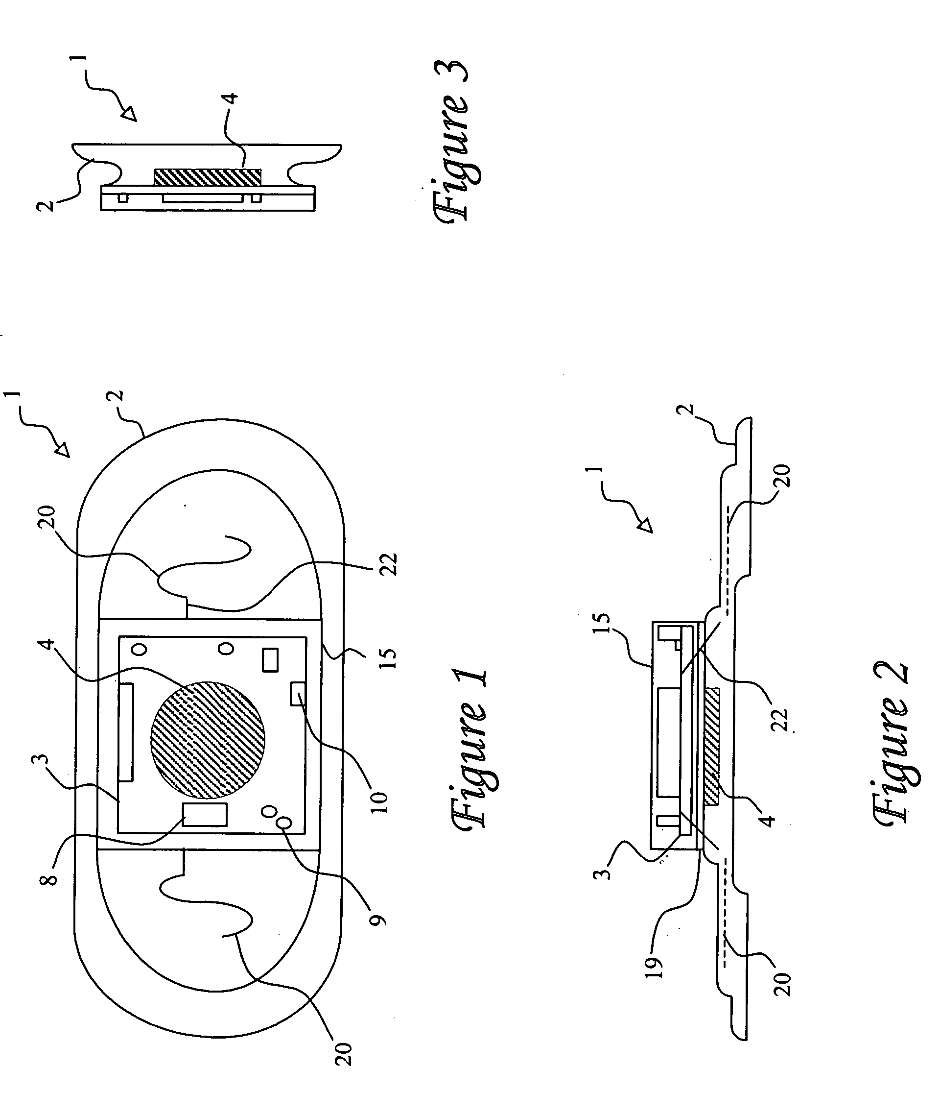
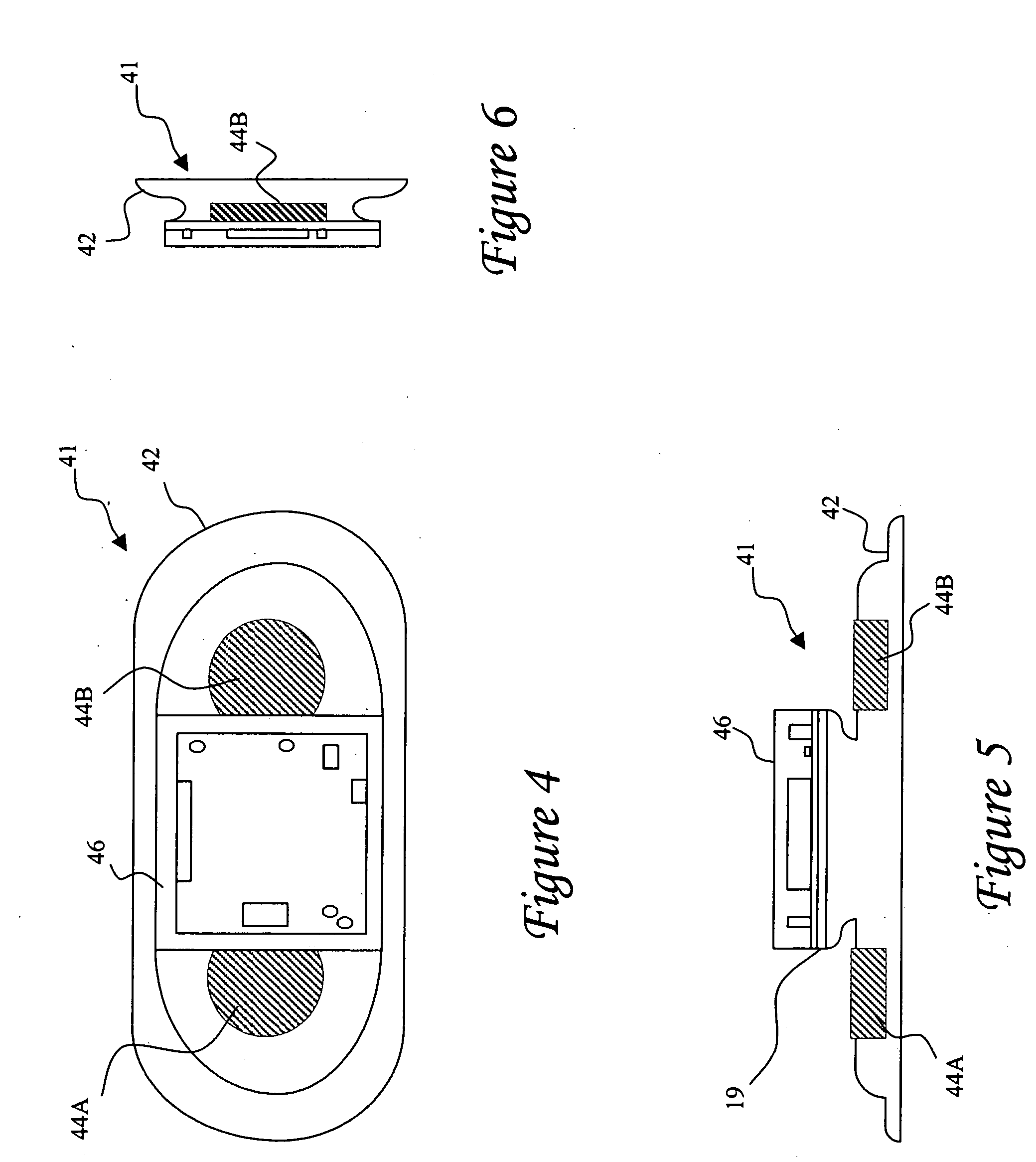
[0036] Reference will now be made in detail to the presently preferred embodiments of the subject matter comprising an improved system and method for mounting an electronics assembly within a tire structure. Selected combinations of the aforementioned aspects of the disclosed technology correspond to a plurality of different embodiments of the present subject matter. It should be noted that each of the exemplary embodiments presented and discussed herein should not insinuate limitations of the present subject matter. Features or steps illustrated or described as part of one embodiment may be used in combination with aspects of another embodiment to yield yet further embodiments. Additionally, certain features may be interchanged with similar devices or features not expressly mentioned which perform the same or similar function. Similarly, certain process steps may be interchanged or employed in combination with other steps to yield additional exemplary embodiments of a method for mo...


PUM


Abstract

A modular electronic assembly for integration with a pneumatic tire includes a mounting patch, a power source, and at least one electronic device supported by a substrate. The mounting patch is preferably adapted for positioning on the inner liner of a pneumatic tire, and the power source is at least partially embedded in the mounting patch. Such embedded positioning of the battery results in an overall structure with a lower center of gravity than previous tire electronics assemblies, thus having increased mechanical stability and survivability in a tire environment. Electronic device(s) supported on the substrate may receive power from the power source, which in some embodiments corresponds to one or more batteries. The substrate supporting the at least one electronic device may be attached to the mounting patch by a variety of fashions. Exemplary attachment configurations may correspond to an adhesive layer, a hook and loop tape combination, or physical interconnection via terminals extending from the power source through the support substrate. Exemplary electronic devices may include such components as condition-responsive devices including transducers, acoustic devices, sensors, etc. for sensing certain environmental conditions such as temperature and/or pressure, tire revolution counters, vehicle speed sensors, sidewall deflection sensors, tire displacement sensors, microprocessors, memory modules, RFID transponders, light assemblies, data transmitters and/or receivers, and power, supply components. Selected of the electronic devices (including one or more antennas associated with any RF devices) may be encapsulated by a non-conductive rubber or elastic material to facilitate effective transmission characteristics. Conductive springs, flexible conductive elastomer or fatigue-resistance metal may be used to interconnect various electronic components (such as an RF device to an antenna).

Description

FIELD OF THE INVENTION [0001] The present invention generally concerns a system and method for installing electrical and electronic components and assemblies in a tire. The subject matter disclosed relates to techniques and apparatus for housing and mounting power source(s), circuit boards, and other electronic devices on and within so called “patch” elements within a tire. BACKGROUND OF THE INVENTION [0002] The incorporation of electronic devices with pneumatic tire structures yields many practical advantages. Tire electronics may include sensors and other components for obtaining information regarding various physical parameters of a tire, such as temperature, pressure, number of tire revolutions, vehicle speed, etc. Such performance information may become useful in tire monitoring and warning systems, and may even potentially be employed with feedback systems to regulate proper tire pressure levels. [0003] A potential capability offered by electronics systems integrated with tire...

Claims


Application Information

Patent Timeline
IPC IPC(8): B60C23/04
CPCB60C23/0493
Inventor METCALF, ARTHUR RICHARDSINNETT, JAY CLIFFORDO'BRIEN, GEORGE PHILLIPS
Owner MICHELIN RECH & TECH SA
Why Eureka
Try Eureka