Friction drive conveyor

a conveyor and friction drive technology, applied in the direction of furniture, charge manipulation, lighting and heating apparatus, etc., can solve the problems of changing the speed of the belt, and achieve the effect of dampening vibrations and ensuring frictional engagemen

Inactive Publication Date: 2005-04-14
JOHN BEAN TECH CORP
View PDF9 Cites 29 Cited by
  • Summary
  • Abstract
  • Description
  • Claims
  • Application Information

AI Technical Summary

Benefits of technology

[0009] A precision conveyor system for transporting products through a plurality of processing areas includes an elongate conveyor structure, a first endless belt having an infeed and an outfeed end and a drive roller or pulley mounted on the conveyor frame about which the endless belt is trained. The drive roller drives the belt through frictional engagement with the belt. The system also includes a belt tensioning and dampening system pivotally mounted on the conveyor frame for applying a tension load on the belt to maintain adequate frictional engagement between the belt and the drive roller and to apply a dampening load on the belt to dampen vibrations occurring in the endless belt.

Problems solved by technology

Also, natural belt resonance can set up oscillations or vibrations in both the infeed and the cutting belts, thereby causing the belt speeds to change.

Method used


Image

  • Friction drive conveyor
  • Friction drive conveyor
  • Friction drive conveyor

Examples


Embodiment Construction

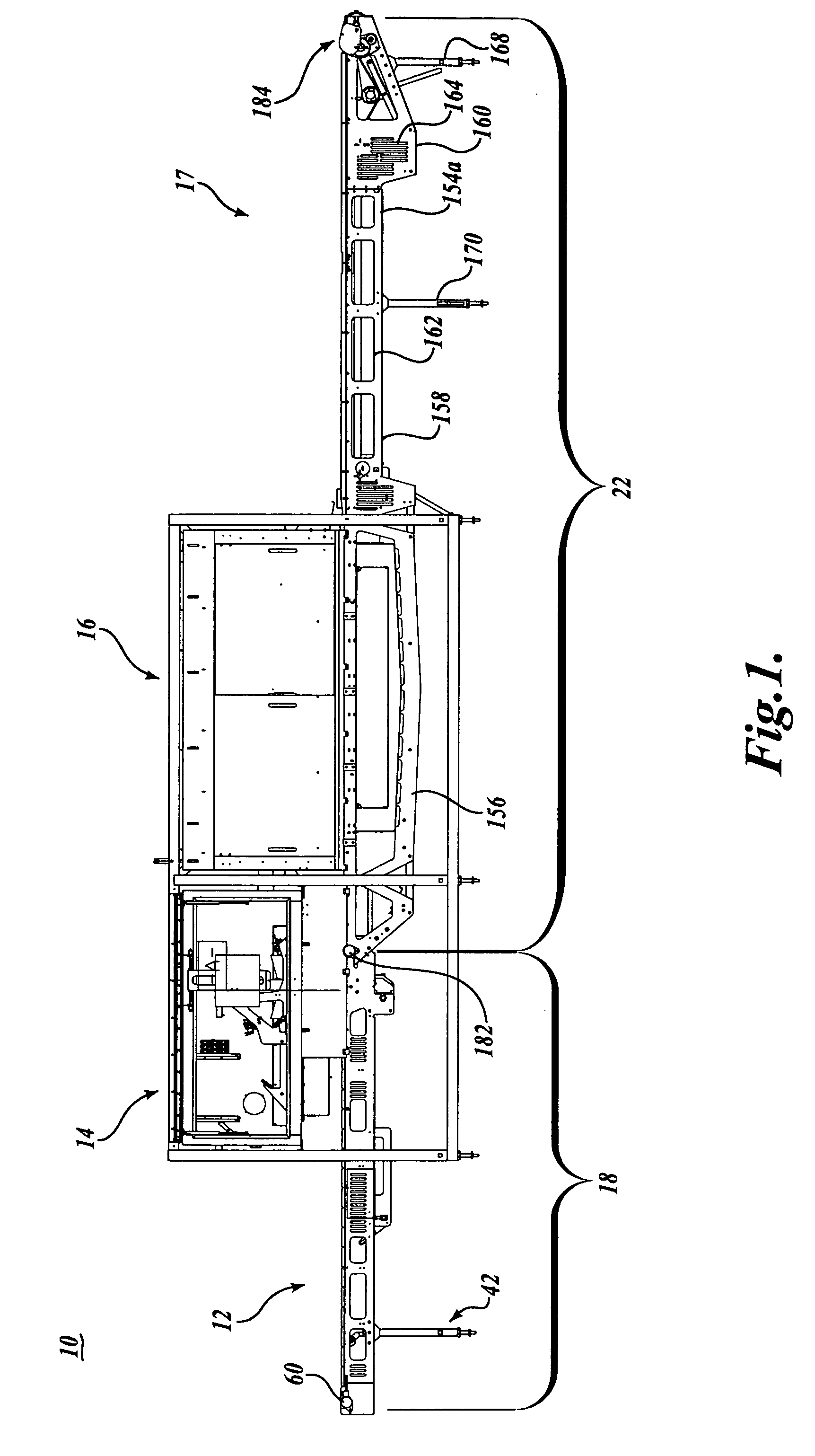
[0029] Referring initially to FIG. 1, the present invention in basic form includes a portioning apparatus 10 composed of a powered conveyor 12 for supporting workpieces to be portioned or trimmed. In the present invention, the terms “upstream” and “downstream” are used with respect to the direction of movement of the conveyor 12. The conveyor 12 carries workpieces past a scanning station 14 where the workpieces are scanned to ascertain selected physical parameters, for example, the size and shape of the workpiece, which information then can be used to determine the weight of the workpiece, typically by using assumed density for the workpiece. Also, during scanning, discontinuities (including voids), foreign material, and undesirable material are located in the workpiece, for example, bones or fat in a meat portion. At the scanning station, the position / location of the workpiece relative to the conveyor is ascertained. The information from the scanner is routed to a control system (n...


PUM

PropertyMeasurementUnit
diameteraaaaaaaaaa
diameteraaaaaaaaaa
tensionaaaaaaaaaa

Abstract

A conveyor 12 includes an infeed / scanning section (18) and a cutting / outfeed section (22). Both sections have an endless belt (70) and (180) each driven by a friction drive roller (100) and (200). Adequate frictional load is applied between the endless belts and corresponding drive rollers by tension assemblies, each having a tensioning roller (86), (188) rotatably mounted on a pivot frame structure (112), (220) allowing the weight of the tensioning roller to be applied to the return run of the endless belts. Dampeners (130) (270) are integrated with the tensioning rollers (86) (188) to dampen vibrations in the endless belts (70) (180).

Description

CROSS-REFERENCE TO RELATED APPLICATION [0001] This application claims the benefit of U.S. Provisional Patent Application No. 60 / 489,151, filed Jul. 21, 2003.FIELD OF THE INVENTION [0002] The present invention pertains to portioning machines, and more particularly to precision conveyor systems for transporting work products through a plurality of processing areas of a portioning machine. BACKGROUND OF THE INVENTION [0003] Workpieces, including food products, are cut or otherwise portioned into smaller portions by processors in accordance with customer needs. Also, excess fat, bone, and other foreign or undesired materials are routinely trimmed from food products. It is often desirable to portion and / or trim the workpieces into uniform sizes, for example, for steaks to be served at restaurants or chicken fillets used in frozen dinners or in chicken burgers. Much of the portioning / trimming of workpieces, in particular food products, is now carried out with the use of high-speed portion...

Claims


Application Information

Patent Timeline
Patent Type & Authority Applications(United States)
IPC IPC(8): A22C17/00A22C18/00B23D47/04B23D51/04B23D55/04B23Q15/02B23Q15/12B26D5/00B26D5/32B26D7/06B26D7/28B26D7/30B65G15/60B65G21/06B65G21/22B65G23/44B65G43/08B65G43/10B65G49/00
CPCB23K26/0003B23K26/0027B23K26/0838B26D5/00B26D5/007B26D5/42Y10S83/932B26D7/28B26D7/30B26F1/382B26F3/004B65G43/08B65G2203/025B26D7/0625B23K26/0006B23K26/351B23K2103/32Y10T83/141B65G21/06B65G23/44
Inventor PFARR, CRAIG E.RUDY, NORMAN A.
Owner JOHN BEAN TECH CORP
Why Eureka
Try Eureka