
Scaling assembly

a technology for scaling and assembly, applied in the direction of manufacturing tools, percussive tools, portable drilling machines, etc., can solve the problems of putting the miners and their equipment in danger, slow method, inefficient, etc., and achieves the effects of reducing labor intensity, reducing labor intensity, and improving efficiency

Active Publication Date: 2005-04-14
ASTEC INDS
View PDF24 Cites 0 Cited by
  • Summary
  • Abstract
  • Description
  • Claims
  • Application Information

AI Technical Summary

Benefits of technology

"The invention is a scaling apparatus that includes a hammer and a pick component with a tooth. The pick component can be moved relative to the hammer to apply a scaling force through the tooth. The pick component has a pivot and the hammer has a pivot that engages with the pick component's pivot. The pick body can also be rotated to apply the scaling force. The invention allows for efficient scaling of objects."

Problems solved by technology

Such instabilities create a risk of roof falls and wall (or pillar) collapse, which may put the miners and their equipment in jeopardy.
This method is slow, inefficient, and can subject the scaling personnel to danger from falling materials.
Another method involves the application of a stream of high-pressure water to the mine roof or walls; however, this method may not remove all fractured materials, and it presents the related problems of providing a supply of water and providing for its disposal.
These machines are typically much faster than manual scaling operations; however, the large forces applied by such machines may create additional stress cracks and other unstable conditions, which may lead to roof falls that damage or block the machines and mine personnel.
In addition, mechanical pick-type scaling machines are more suited to use in layered rock formations such as limestone, and may not be efficient when used in other types of formations.
Such breaker-style machines generally do not permit good visibility of the working surface by the operator, and they can also result in the application of too much energy to the rock, causing additional stress cracks (which require additional scaling) and falls.
Consequently, such machines may create severe reaction forces in the knuckle joints of the boom, leading to excessive wear and vibration and a reduced service life.

Method used


Image

  • Scaling assembly
  • Scaling assembly
  • Scaling assembly

Examples


Embodiment Construction

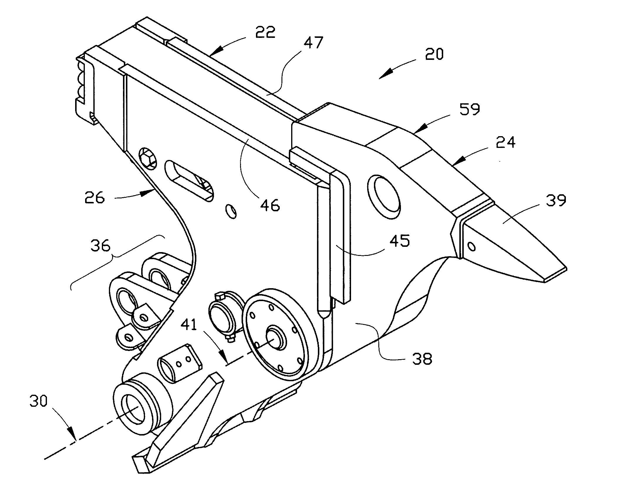
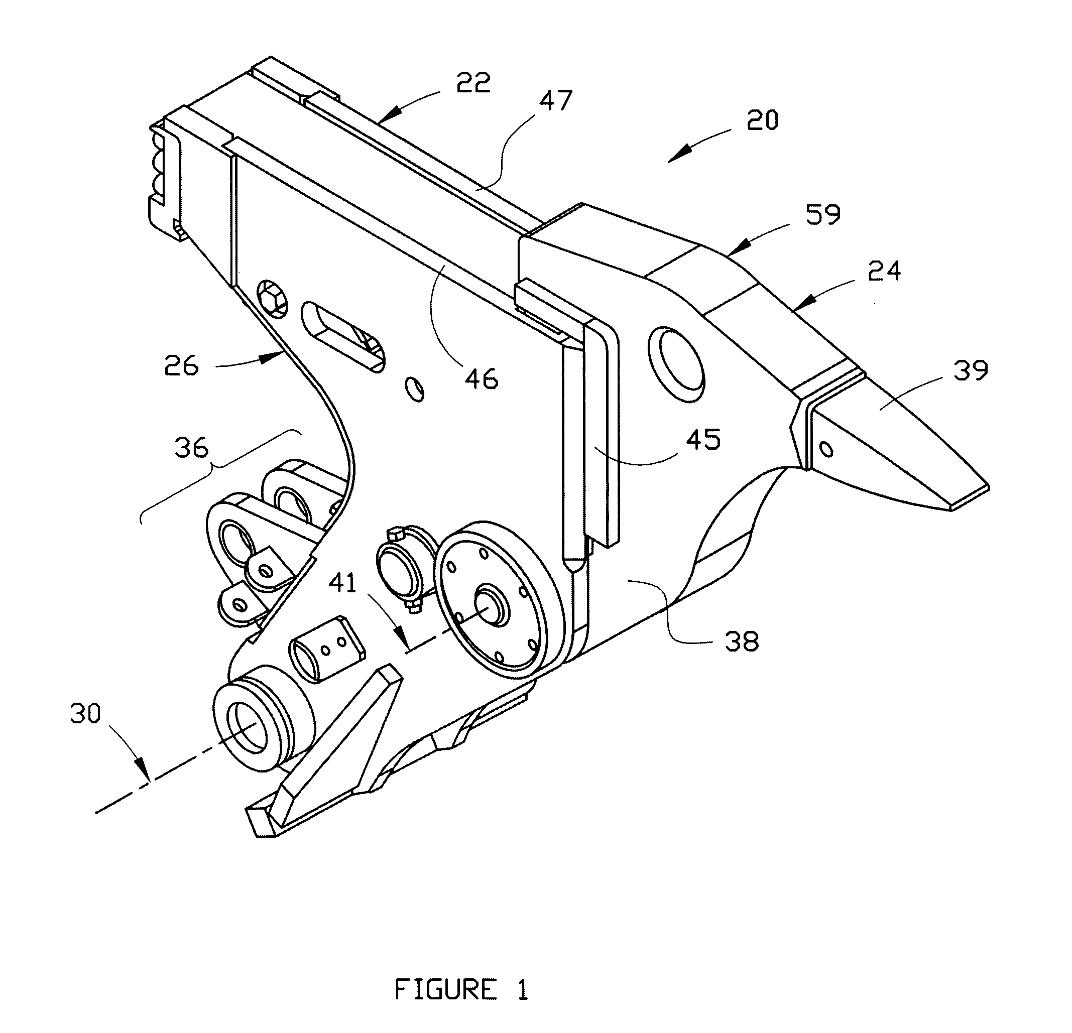
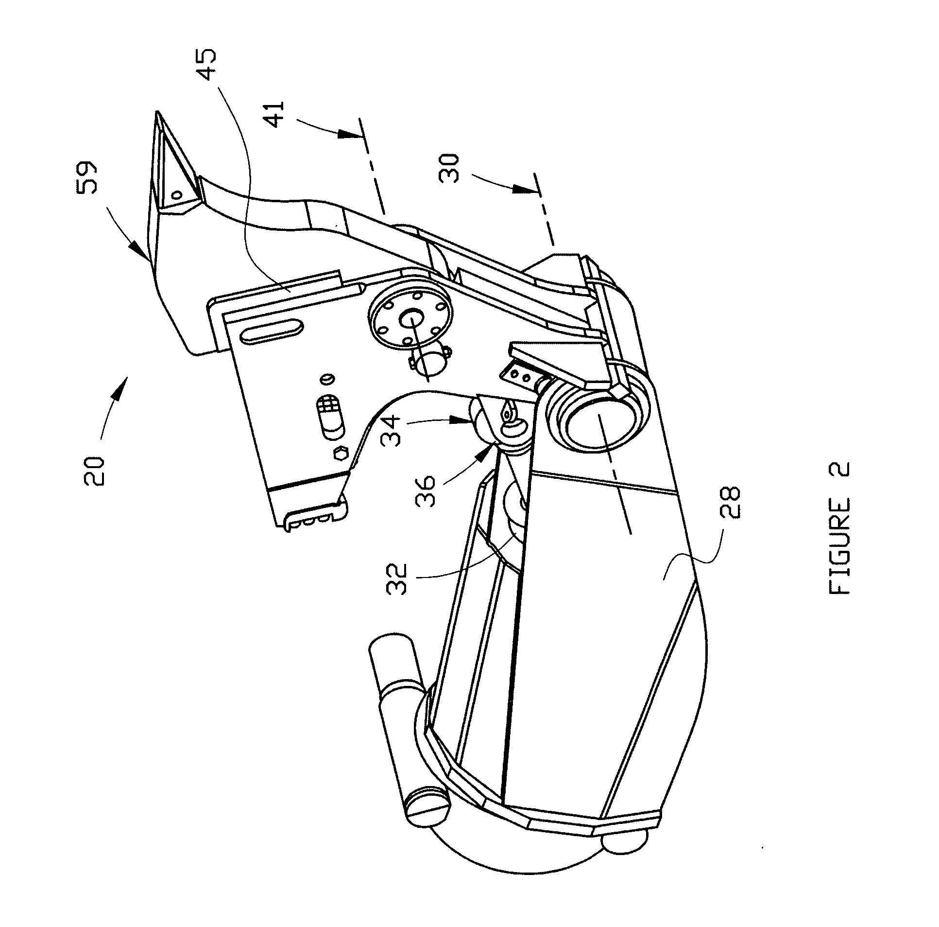
[0030] Referring now to the drawings, a preferred embodiment of the invention, comprising scaling assembly 20, is shown in FIGS. 1, 2 and 5-7. Assembly 20 includes hammer component 22 and pick component 24. The hammer component includes hammer housing 26 that is preferably adapted to be pivotally attached to a boom such as boom 28 (a portion of which is shown in FIG. 2) so that it may be rotated about boom pivot axis 30. Preferably, scaling assembly 20 is rotatably positioned with respect to boom 28 by hydraulic actuator 32 (a portion of which is shown in FIG. 2) having rod end 34 that is pivotally attached to clevis 36 of assembly 20. Pick component 24 includes pick body 38 and tooth 39, which is mounted on the pick body. As shown in FIG. 3, an alternative embodiment of pick body 138 includes pick teeth (or ground engaging teeth) 139, 140 and 141. Other arrangements of teeth on the pick body as would be obvious to those having ordinary skill in the art to which the invention relate...


PUM

PropertyMeasurementUnit
angle of rotationaaaaaaaaaa
angleaaaaaaaaaa
angleaaaaaaaaaa

Abstract

A scaling apparatus comprises a hammer component and a pick component which includes a tooth. The apparatus also includes a mechanism for moving the pick component with respect to the hammer component to thereby impart a scaling force to and through the tooth. In a preferred embodiment of the invention, the pick component includes a pick body comprising a first pivot having a pivot axis and a tooth mounted on the pick body. In this embodiment of the invention, the hammer component includes a hammer housing and a second pivot mounted within the housing and adapted to pivotally engage the first pivot of the pick body. This embodiment of the invention also includes means for rotating the pick body relative to the hammer component so as to impart a scaling force.

Description

CROSS REFERENCE TO RELATED APPLICATION This application claims the benefit of U.S. Provisional Application No. 60 / 510,531, which was filed on Oct. 14, 2003.FIELD OF THE INVENTION [0001] This invention relates generally to an apparatus for use in scaling operations in connection with underground mining, in which loose and fractured material may be removed from the roof and walls of the mine in a safe manner. The invention may also be used in removing slag and scale from inside ladles and other items of equipment used in metallurgical processes. BACKGROUND AND DESCRIPTION OF THE PRIOR ART [0002] In underground mining operations, an access tunnel is bored into or beneath the earth, and miners and their equipment are introduced to extract coal, limestone, precious metals and other minerals from product-bearing seams. Such mining operations may involve blasting into the face of a seam and / or the use of digging equipment to dig into the face. Such activities create instabilities in the wa...

Claims


Application Information

Patent Timeline
Patent Type & Authority Applications(United States)
IPC IPC(8): E21C37/22
CPCE21C37/22
Inventor WITTENBERG, JOHNMORNEAULT, PAUL
Owner ASTEC INDS
Learn More