
Microwave tube system and microwave tube

a technology of micro-wave tubes and tubes, applied in the field of micro-wave tubes, can solve the problems of blocking the discharge current that flows between the cathode electrode and the anode electrode, and blocking the excess current that flows to the helix, so as to prevent unnecessary halts of operation

Active Publication Date: 2005-04-14
NEC NETWORK & SENSOR SYST
View PDF4 Cites 5 Cited by
  • Summary
  • Abstract
  • Description
  • Claims
  • Application Information

AI Technical Summary

Benefits of technology

[0021] It is an object of the present invention to provide a microwave tube system and microwave tube in which the easy output of an alarm signal is suppressed to allow prevention of unnecessary halts of operation.
[0024] Accordingly, the provision of a current suppression element can shorten the continuous interval of time of flow of an excess current to the helix that is caused by discharge, and thus can prevent shortening of the operating life of the microwave tube that results from damage to the helix caused by the flow of excess current and a decrease in the insulative capacity between electrodes. The provision of the current suppression element can also suppress the easy output of alarm signals resulting from discharges that occur in the microwave tube, and thus can prevent unnecessary operation halts of the microwave tube system.
[0025] In particular, if a resistor is used as the current suppression element, the mere addition of this relatively small part can suppress the continuous time interval of flow of an excess current to the helix that is caused by discharge, and can therefore limit increase in the bulk and weight of the microwave tube.

Problems solved by technology

As a result, the discharge current that flows between the cathode electrode and anode electrode is blocked, and the excess current that flows to the helix is also blocked.

Method used


Image

  • Microwave tube system and microwave tube
  • Microwave tube system and microwave tube
  • Microwave tube system and microwave tube

Examples


Embodiment Construction

[0029] Explanation next regards the present invention with reference to the accompanying figures.

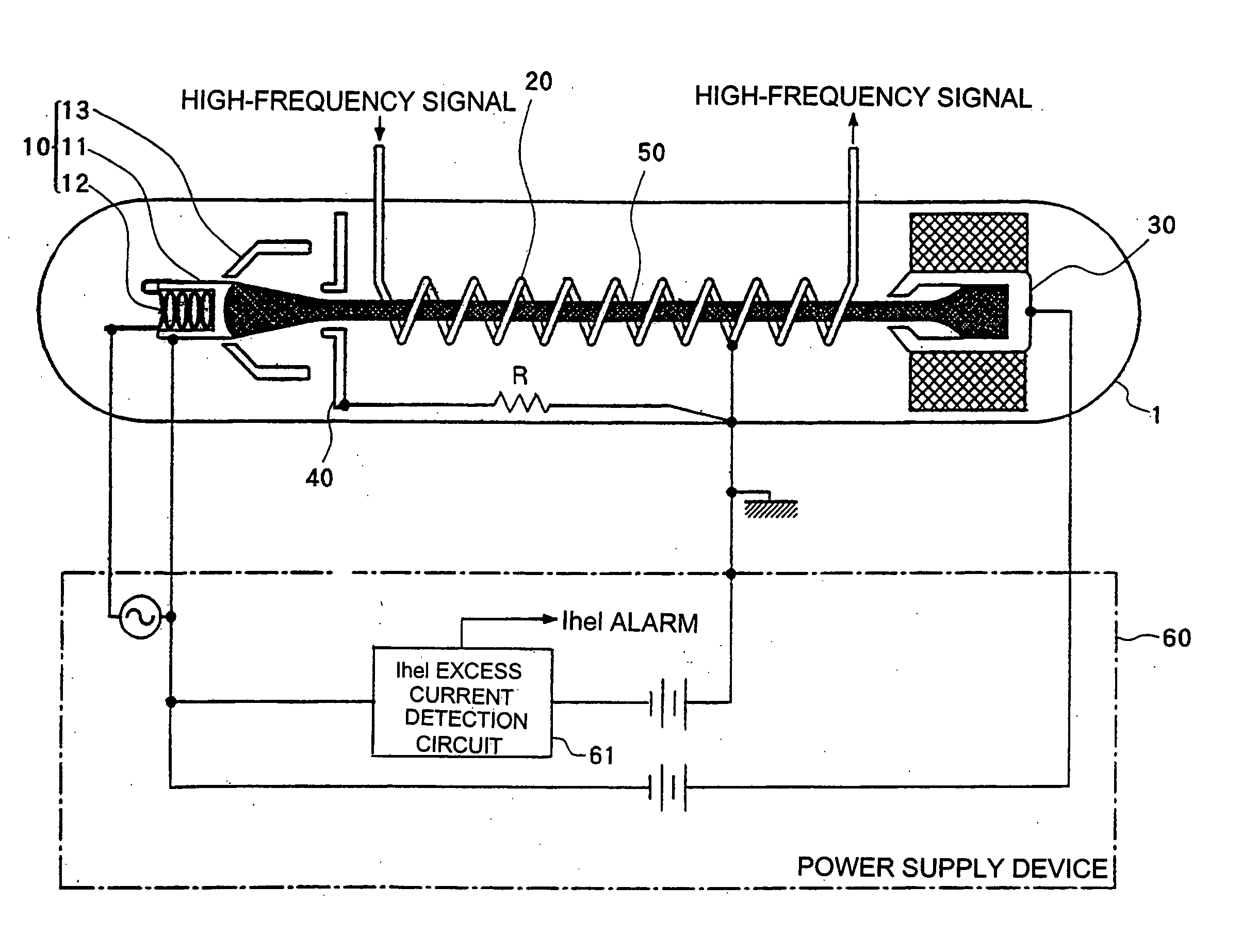
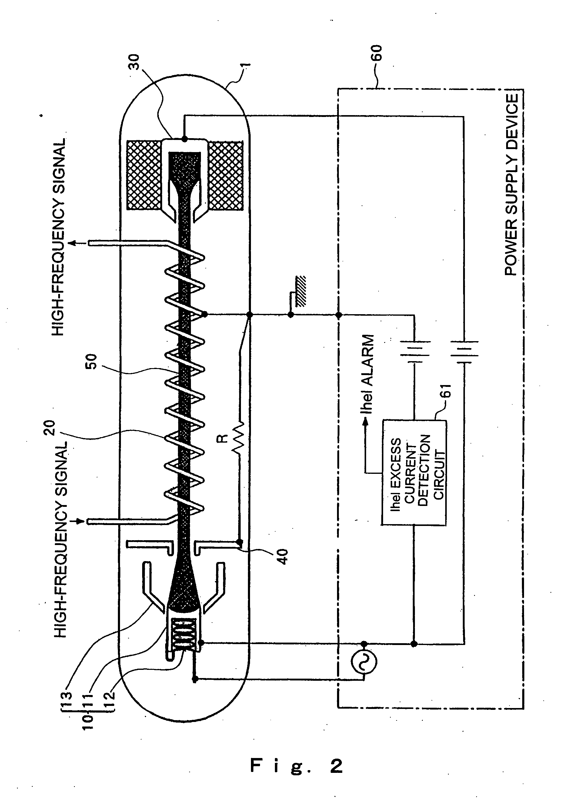
[0030] As shown in FIG. 2, the microwave tube of the present invention is a configuration in which the connection between anode electrode 40 and helix 20 of microwave tube 1 of the prior art shown in FIG. 1 is cut off, helix 20 is connected to the case of microwave tube 1 and thus grounded, and a current suppression element is inserted between anode electrode 40 and the case (ground voltage) of microwave tube 1.

[0031] A component such as resistor R is used as current suppression element, and this resistor R is accommodated inside the case of microwave tube 1. Common lead lines that are used for supplying the same voltage to anode electrode 40 and helix 20 are lead out from microwave tube 1. The configuration of microwave tube 1 and power supply device 60 is otherwise identical to that of the microwave tube system of the prior art that is shown in FIG. 1, and explanation of this configu...


PUM


Abstract

A microwave tube has a configuration in which the connection between an anode electrode and the helix is cut, the helix is grounded, and a current suppression element is provided between the anode electrode and ground voltage for suppressing the continuous time interval of the flow of an excess current to the helix that is caused by discharge to a time interval range that does not threaten damage to the helix, i.e., to a time interval range in which an alarm signal is not supplied.

Description

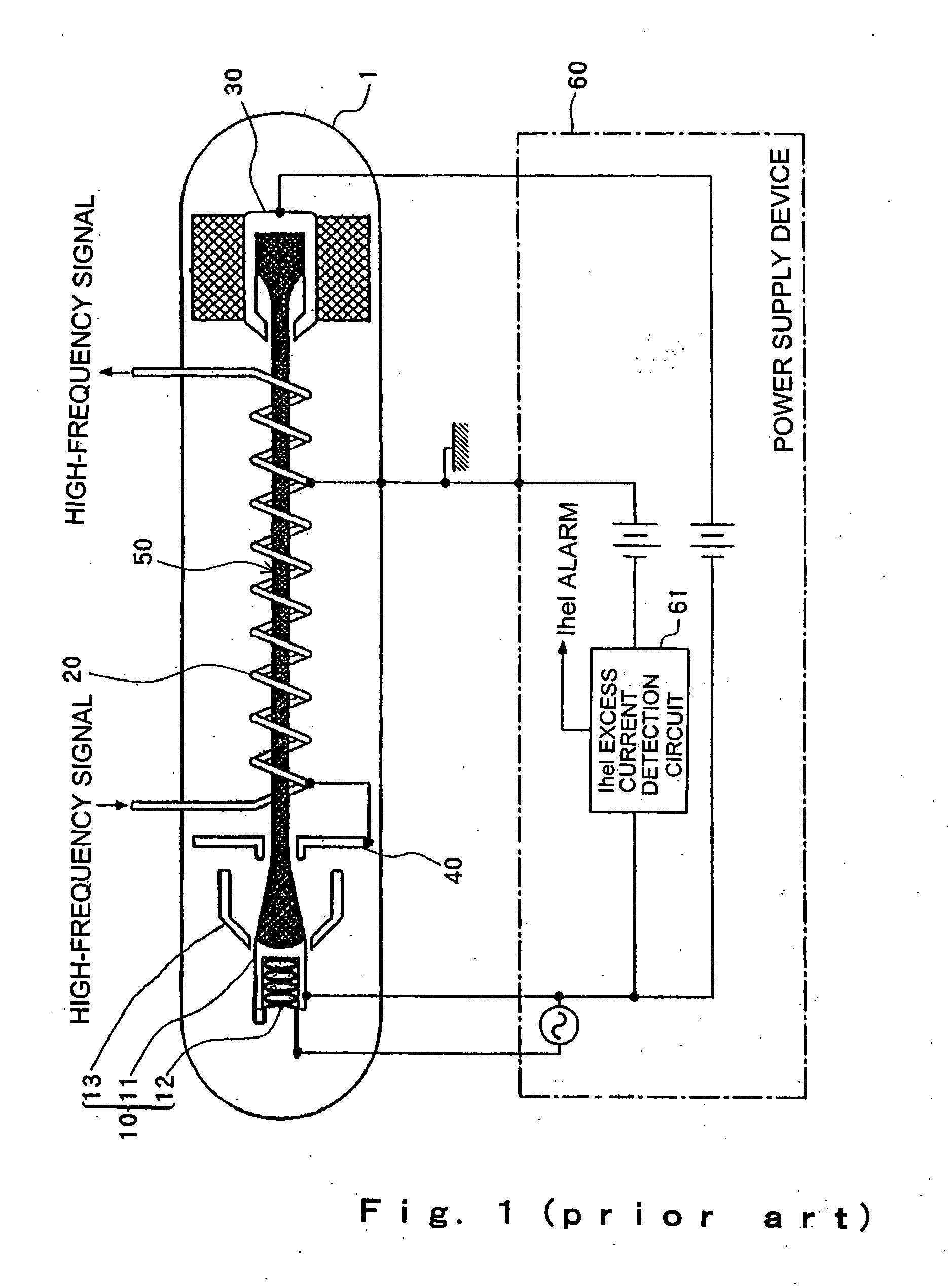
BACKGROUND OF THE INVENTION [0001] 1. Field of the Invention [0002] The present invention relates to a microwave tube such as a klystron or traveling-wave tube that is used in the amplification and oscillation of a high-frequency signal, and to a microwave tube system that is provided with a power supply device for supplying a prescribed power supply voltage to each electrode of the microwave tube. [0003] 2. Description of the Related Art [0004] A microwave tube such as a klystron or a traveling-wave tube is an electron tube that realizes the amplification and oscillation of a high-frequency signal through the interaction between a high-frequency circuit and an electron beam that is emitted from an electron gun. As shown in FIG. 1, such a microwave tube is a construction that includes: electron gun 10 for emitting electron beam 50; helix 20, which is a high-frequency circuit for causing interaction between electron beam 50 that is emitted from electron gun 10 and a high-frequency si...

Claims


Application Information

Patent Timeline
Patent Type & Authority Applications(United States)
IPC IPC(8): H01J23/34H01J25/00H01J25/34
CPCH01J25/34H01J23/34
Inventor TSUCHIDA, HIROSHI
Owner NEC NETWORK & SENSOR SYST
Learn More