Facilities management system

a technology of facilities management and management system, applied in the field of facilities management system, can solve the problems of gaining unauthorized access, reducing security, and reducing security, so as to increase security, increase management control and efficiency, and improve security

Inactive Publication Date: 2005-04-14
HUTCHINS J MARC +1
View PDF9 Cites 213 Cited by
  • Summary
  • Abstract
  • Description
  • Claims
  • Application Information

AI Technical Summary

Benefits of technology

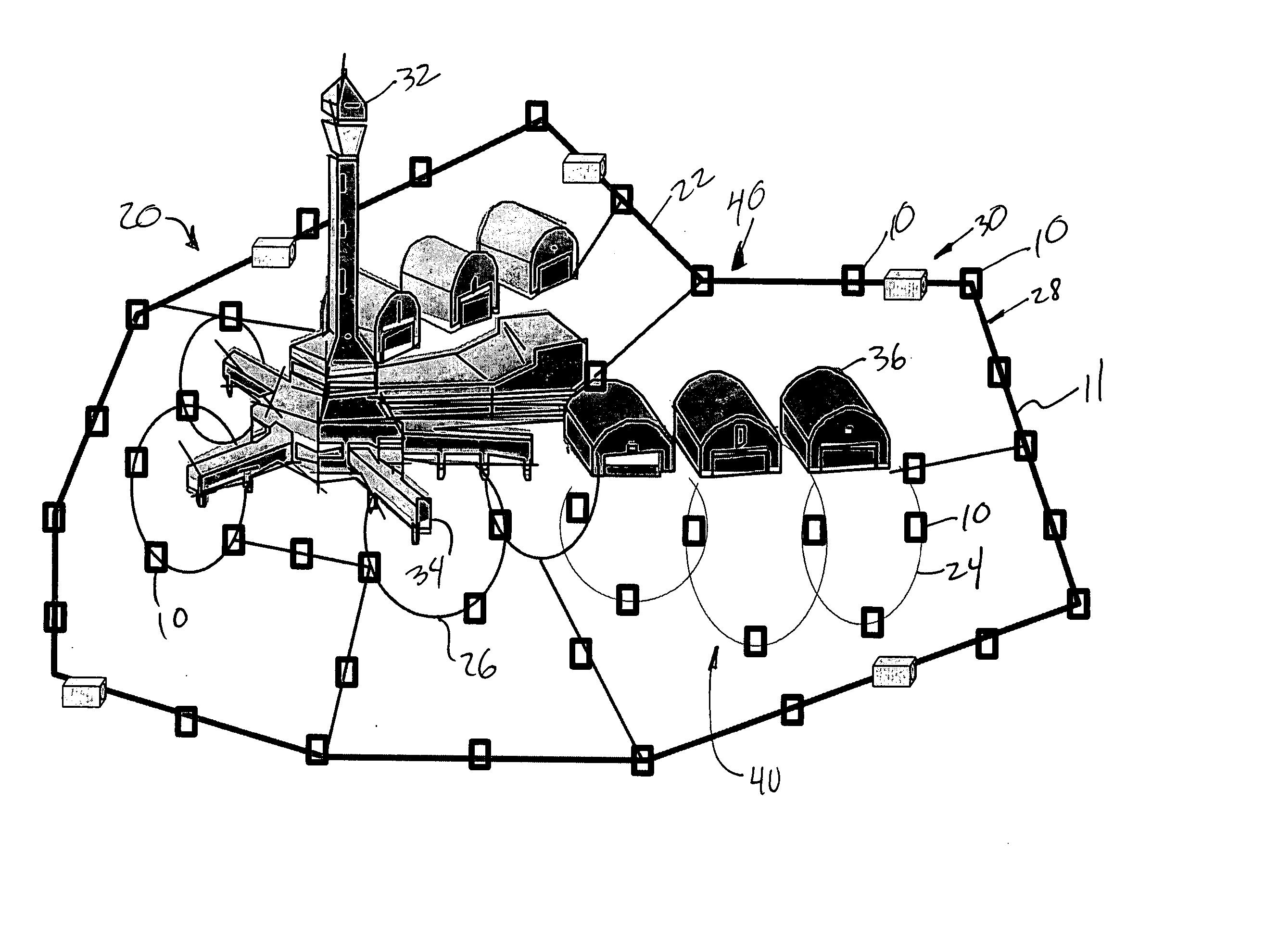
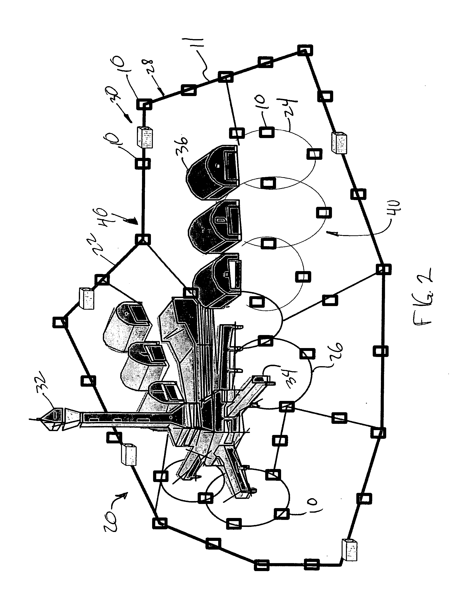
[0013] Specifically with respect to the “surveillance paths”, such paths may be definable by embodiments of the present invention in order to monitor the movement in more linear shaped areas or boundaries or borders such as along the centerline of taxiways and runways or along a pathway. Any vehicle or aircraft that deviated from a pre-identified route would be detected by the systems. All tagged entities, vehicles, aircraft, people, and even tagged items may be tracked and timed as they travel the prescribed surveillance paths. The readers, if encapsulated in the directional lighting elements may also provide a convenient means for mitigating runway incursions as all aircraft and vehicle locations and identifications would be known and tracked and could be guided by / to via specific paths to specific areas. Non-conforming vehicles, as in a newly arrived aircraft without an authorized tag, and therefore not known by the processor of the system, would be detected by the passive sensors linked to the system and the central processor may communicate this status so that appropriate action may be taken. An aircraft in such a situation may be more carefully chaperoned by air traffic control and other vehicles and people in the system may be notified in order to avoid such aircraft. The present invention may permit communications with sensors and recorders of the management system in order, for example, to track and record the non conforming aircraft and time and record its progress from sensor to sensor, or from light guidance to light guidance or both, to increase security, safety, as well as helping in time management efficiency studies and implementation of more management control and efficiency.
[0014] The central processing component of the system is preferably configurable so that tagged entities or targets—such as tagged vehicles, personnel, or items—may be monitored over “time” and their location identified. For example, baggage being transported between terminals on a transport vehicle may be monitored so that the path that the vehicle is taking can be identified and compared with an expected path, to determine whether the vehicle is deviating from that ideal path. Also, the amount of time that the vehicle is taking to make the trip can be determined by comparison of elapsed times between the frequent reader checkpoints placed in an area or along an expected path. Security, safety, and efficiency are thereby enhanced, since if a baggage transport vehicle strayed from its designated path it would be detectable. Similarly, if the vehicle for whatever reason took too long before being checked in by the next reader, it would be detected and an alarm could be activated for appropriate authorities to investigate. On a larger scale, if a task took too long to achieve (taking the baggage vehicle from one terminal to the next), it would also be detected and appropriate authorities notified. As such the management system of the present invention may be used to improve security, to facilitate actions taken because of an emergency, a runway incursion avoidance system, a guidance system, an efficiency time management system, and an inventory system.
[0015] Advantageously, the technology used to monitor the security areas, such as the surveillance rings and paths, may be complementary, and therefore be easily integrated into security systems already in place to monitor limited areas such as doorways and gateways to expand overall security. Similar integration can occur with vehicle guidance systems, and management control and efficiency or inventory tools, so that the area or airport as a whole is more secure, safer, and becomes more efficient.
[0016] Further advantageously, the technology may be manufactured at such a cost and have less energy requirements such that the system overall may be relatively less expensive, more reliable, and lightweight product used for a wide variety of applications and solutions. The technology for these applications is unobtrusive and often so seamless, that most users are unaware of its presence.
[0017] Advantageously, the system of readers and tags permits the monitoring of potentially irregular, concentric perimeter areas for the simultaneous identification of multiple RFID tags. Known systems only permit “access control”—that is, control of access through limited areas such as doorways and gates, while the present invention permits “freedom of movement” with full monitoring of simultaneous multiple RFID tag users.
[0018] Advantageously, the system of readers and tags permits the management of potentially all personnel, vehicles, items and other tagged entities within a large identified area, in order, for example, to increase security and safety for all those using the area in which it is installed and be easily integrated as a management tool to increase the efficiency of the airport, or any other area in which it is installed.

Problems solved by technology

While apparatus are known for identifying, authenticating, monitoring, tracking, controlling, and managing individuals, vehicles, and materials moving through limited areas of egress and ingress—such as paths, gates, doors, and other exits and entryways—termed “portals” for purposes of this application, achieving the same level of control for vast open and irregularly shaped operations areas—such as, but not limited to airport tarmacs and airport movement areas—is much more difficult.
However, such physical barriers may be defeated and unauthorized access gained.
Physical barriers also tend to impede movement in such areas.
However, such surveillance requirements may not be practicable for large areas and may require one or more individuals to continuously observe the screens on which the images from the surveillance cameras are transmitted.
This is a time consuming and labor intensive task requiring constant vigilance.
However, if the task is not performed, unauthorized access may be achieved and undocumented.

Method used


Image

  • Facilities management system
  • Facilities management system
  • Facilities management system

Examples


Embodiment Construction

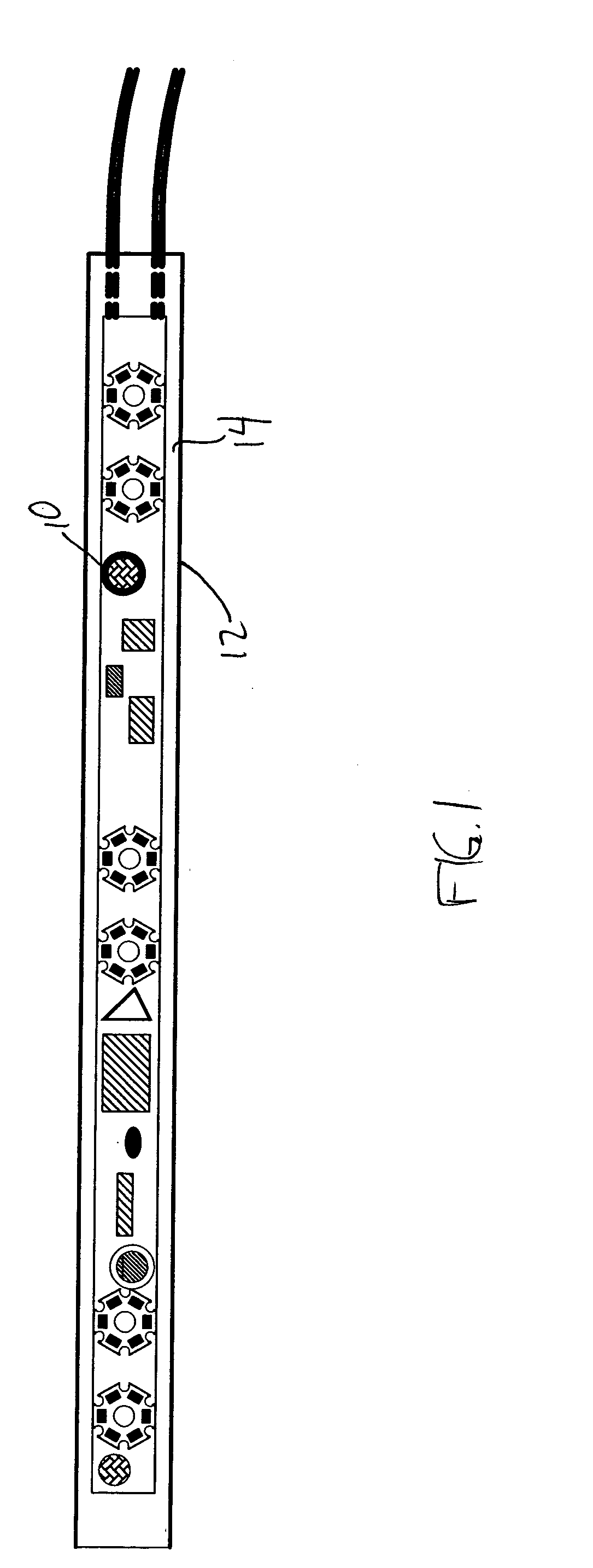
[0040]FIG. 1 illustrates one embodiment of an enclosure 12 including a read / write device 10 for use in the facilities management system according to this invention. The read / write device 10 is thus well adapted for use in stressful environments, such as roadways, waterways, landing strips, high traffic walkways, warehouses, and the like. When so deployed, the device 10 is preferably encapsulated and / or potted in the enclosure 12, enclosed or contained therein. The enclosure 12 may be a plastic housing or formed of another suitable material, with or without a gasket to provide a seal 14 to the enclosure or an extruded, cast, molded enclosure or the like.

[0041] The read / write device 10 functions as a tag sensor, which is an electronic device for sensing, reading, identifying and, optionally writing to a tag, such as a RFID tag (not shown). Other such electronic devices, which may be arranged on the enclosure 12, include transmitters, antennae, LEDs, and various other sensors as descr...


PUM


Abstract

A system is described for management of an operations area. The management system includes a central processing component with one or more central processors. An active monitoring system component is connected to the central processor. The active monitoring system includes tags and readers for individual identification of one or more tagged entities. The active monitoring system component is arrayed to create a management zone. The tags and readers are linked to the central processing component such that information from the tags and readers is received and analyzed by the central processing component. A passive monitoring system component is connected to the central processor. The passive monitoring system identifies non-tagged entities entering the management zone and additional information is communicated to the central processing component for analysis.

Description

[0001] This application claims benefit of U.S. Provisional Application No. 60 / 348048, filed November 20, 2001.TECHNICAL FIELD [0002] The present invention is directed to a system for management of an operations area. Generally, the system includes a central processing component and a monitoring system that includes an active monitoring system component including electronic tags and read / write sensors for identification of tagged assets, and a passive monitoring system component for identification of non-tagged entities. The system may be used to monitor large areas or facilities, such as airports, and sub-areas nested or associated with the large areas. The system may also be utilized in areas of ingress and / or egress such as gates, portals or doors, or in urban areas around secure facilities, office buildings, factories, or any other areas where control of resources or assets is important. BACKGROUND OF THE INVENTION [0003] Areas—such as campuses or ranges—, facilities—such as such...

Claims


Application Information

Patent Timeline
Patent Type & Authority Applications(United States)
IPC IPC(8): G07C9/00
CPCG08B13/2454G07C9/00111G07C9/28
Inventor HUTCHINS, J. MARCHUTCHINS, NICHOLAS D
Owner HUTCHINS J MARC
Why Eureka
Try Eureka