
Method and apparatus for improving power efficiencies of computer systems

a technology of computer system and power efficiency, applied in the direction of lighting and heating apparatus, insulated conductors, cables, etc., can solve the problems of increasing the power consumption affecting so as to achieve the effect of improving the overall power efficiency of the computer system, reducing and improving the power density of the computer chips

Inactive Publication Date: 2005-04-14
IBM CORP
View PDF13 Cites 33 Cited by
  • Summary
  • Abstract
  • Description
  • Claims
  • Application Information

AI Technical Summary

Benefits of technology

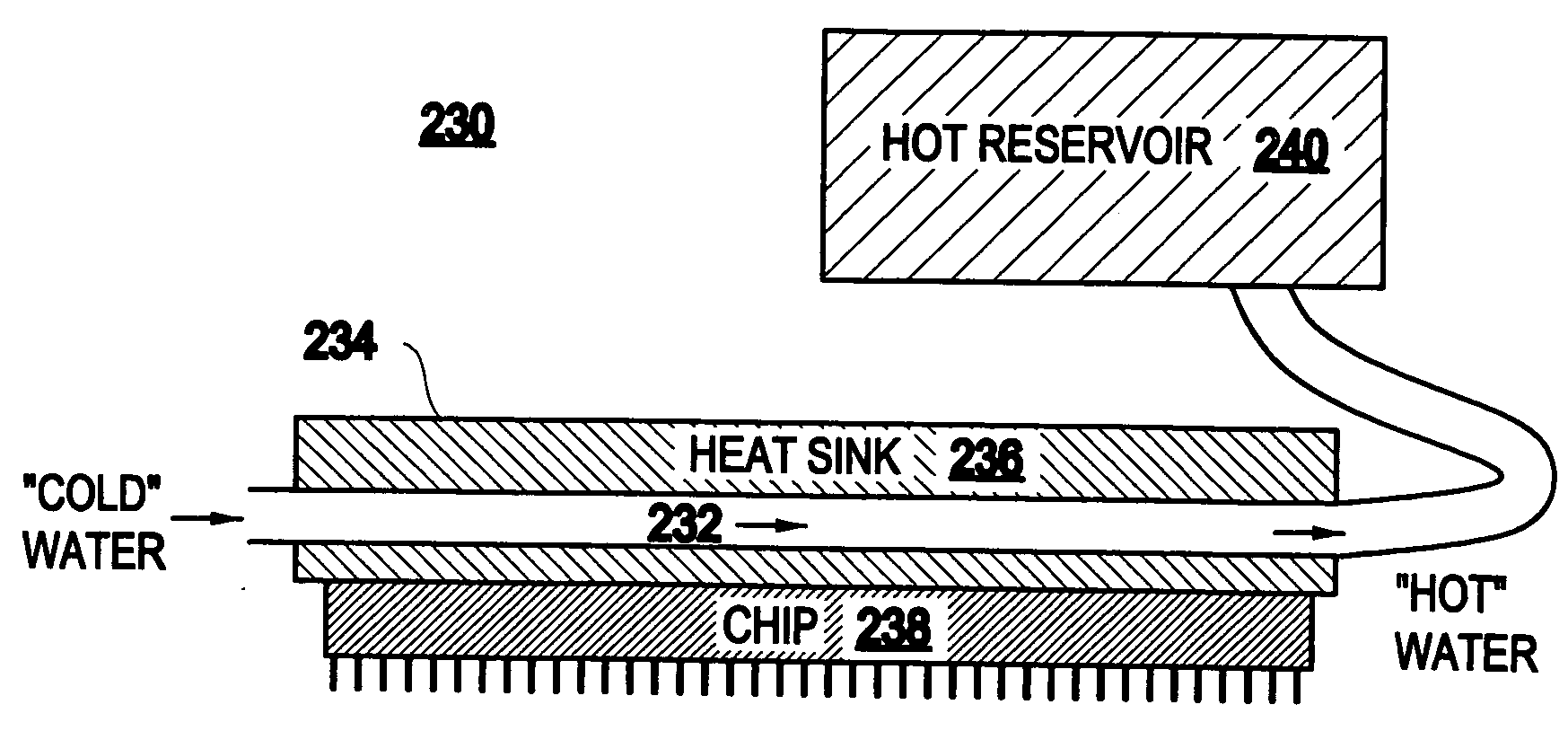
The present invention provides a method and structure for improving the power efficiency of computer systems. It involves recycling the heat generated by microprocessors and directing the heat to cool the microprocessor and / or supplying power to an electric power grid. This results in overall improved power efficiency of computer systems. The invention recognizes that a significant fraction of the total power is consumed by only a few computer chips, and the power density in these computer chips is remarkably high. By recycling the heat and directing it to a heat engine, the invention reduces the thermal loading of the microprocessor and lowers the overall power consumption of computer systems.

Problems solved by technology

With ˜10 cents per kWh, each mainframe computer results in more than $10K of utility costs per year, which represents a significant fraction of the total costs to run a mainframe computer.
In the future, these utility costs for computer systems are projected to rise even higher as processors become more powerful and as device dimensions in microprocessor decrease.
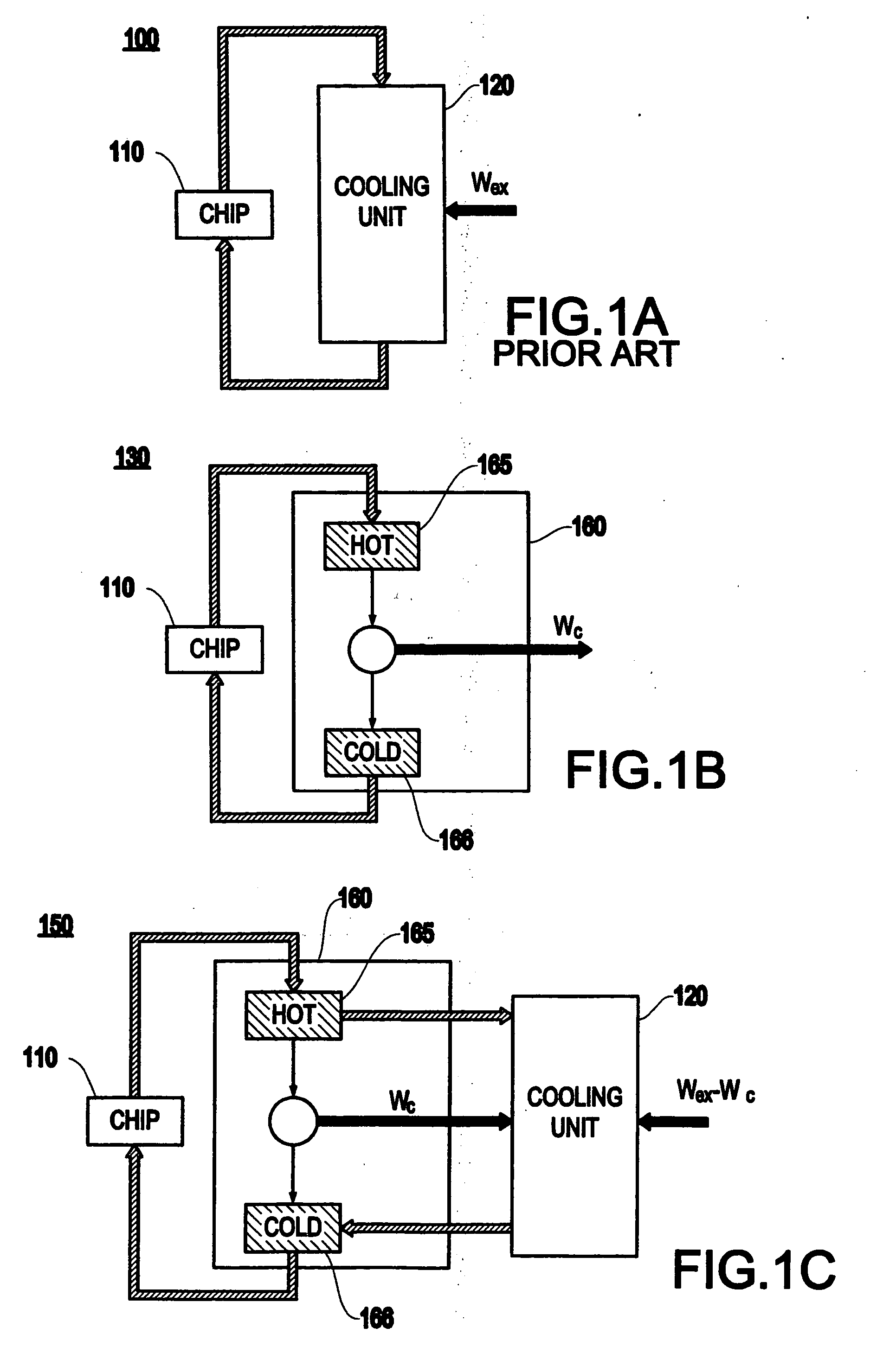
The energy Wex for driving the fan is obtained from an external source, thereby adding even more to the power consumption of the computer system.
The fraction of the utility costs is increasing to a prohibitive level, as time progresses.
Hence, more and more of the costs for operating a data center will have to be dedicated to the utility costs.
Indeed, the need for power is expected to grow so large that conceivably an entire, dedicated power plant may be needed to operate and meet the data center's electrical needs since there may not be enough power locally to meet the data center's power requirements.
Thus, not only will there be an increase in day-to-day current needs, but also a large potential infrastructure cost may be expected.

Method used


Image

  • Method and apparatus for improving power efficiencies of computer systems
  • Method and apparatus for improving power efficiencies of computer systems
  • Method and apparatus for improving power efficiencies of computer systems

Examples


Embodiment Construction

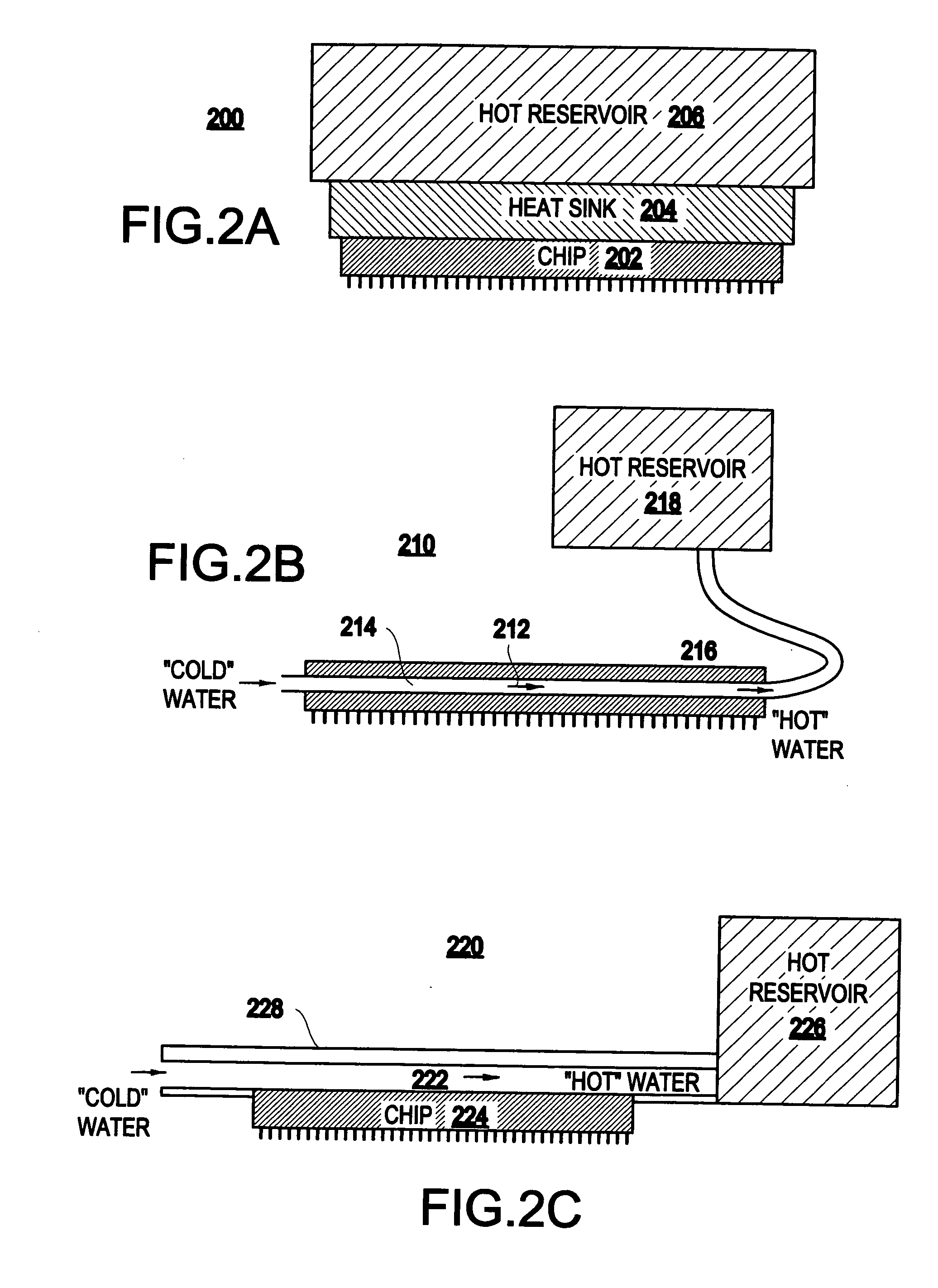
[0027] Referring now to the drawings, and more particularly to FIGS. 1A-5, there are shown exemplary embodiments of the method and structures according to the present invention.

[0028] Exemplary Embodiment

[0029] Hereinbelow, an exemplary structure of a Carnot heat engine is used according to the present invention.

[0030] By way of contrast to the conventional system 100 shown in FIG. 1A, the present invention realizes that: 1) a significant fraction of the total power is consumed by only a few computer chips (e.g., microprocessors); 2) the power density in these computer chips is remarkably high and thus can be readily directed towards a heat engine without thermally loading the computer chips; and 3) at least some of the heat can be recycled to lower the overall power consumption of computer systems.

[0031]FIG. 1B illustrates one basic aspect of a system 130 of the present invention. The heat from at least one microprocessor 110 is directed towards means for recycling heat to ener...


PUM


Abstract

An assembly (and method) including at least one microprocessor, includes a mechanism for recycling heat generated by at least one microprocessor to energy, and a mechanism for directing the heat from the at least one microprocessor to the mechanism for recycling heat. The energy generated by the mechanism for recycling the heat can be used to cool the at least one microprocessor or to supply an electric power grid.

Description

CROSS-REFERENCE TO RELATED APPLICATION [0001] The present application is related to U.S. patent application Ser. No. ______, filed on ______, to Robert Jacob von Gutfeld, entitled “APPARATUS AND METHOD FOR UTILIZING RECIRCULATED HEAT TO CAUSE REFRIGERATION” having IBM Docket No. YOR920030071US1, assigned to the present assignee, and incorporated herein by reference.BACKGROUND OF THE INVENTION [0002] 1. Field of the Invention [0003] The present invention generally relates to a method and an apparatus suitable for improving the power efficiencies of computer systems. [0004] 2. Description of the Related Art [0005] For the year 2004, it is projected that more than ˜5% of the total power needed in the U.S. is consumed just alone in data centers, which is typically realized by large assemblies of mainframe computers and data storage systems. [0006] More specifically, an IBM mainframe computer system requires ˜(20-30) kW (excluding any additional power consumption due to air conditioning ...

Claims


Application Information

Patent Timeline
Patent Type & Authority Applications(United States)
IPC IPC(8): H01L23/38H01L23/473H05K7/20
CPCH01L23/38H01L23/473H01L2924/0002H01L2924/00
Inventor HAMANN, HENDRIK F.KESSEL, THEODORE G. VANGUTFELD, ROBERT JACOB VON
Owner IBM CORP
Learn More