
Biopsy site marker

a biopsy site and marker technology, applied in the field of subcutaneous cavity marking devices and methods, can solve the problems of clip detachment from the cavity wall, device has significant drawbacks, initial biopsy failed to remove a sufficient amount of lesion, etc., and achieve the effect of minimizing any “dimpling effect”

Inactive Publication Date: 2005-04-14
DEVICOR MEDICAL PROD
View PDF99 Cites 82 Cited by
  • Summary
  • Abstract
  • Description
  • Claims
  • Application Information

AI Technical Summary

Benefits of technology

[0016] The device may additionally contain a variety of drugs, such as hemostatic agents, pain-killing substances, or even healing or therapeutic agents that may be delivered directly to the biopsy cavity. Importantly, the device is capable of accurately marking a specific location, such as the center, of the biopsy cavity, and providing other information about the patient or the particular biopsy or device deployed.
[0022] Both the body and the marker can be made, via radiopaque or echogenic coatings or in situ, to degrade and absorb into the patient's body over a predetermined period of time. It is generally preferred that if the marker's radiopacity or echogenicity is chosen to degrade over time, such degradation does not take place within at least one year after implantation of the inventive device. In this way, if a new lump or calcification (in the case of a breast biopsy) is discovered after the biopsy, such a marker will allow the physician to know the relation of such new growth in relation to the region of excised tissue. On the other hand, and as discussed below, a bioabsorption period of three months is preferred for any such coatings on the perimeter of the body itself.
[0027] In contrast to the marker clips as described above, the cavity marking device has the obvious advantage of marking the geometric center of a biopsy cavity. Also, unlike the marking clip which has the potential of attaching to loose tissue and moving after initial placement, the marking device self-expands upon insertion into the cavity, thus providing resistance against the walls of the cavity thereby anchoring itself within the cavity. The marking device may be configured to be substantially smaller, larger, or equal to the size of the cavity; however, in some cases the device will be configured to be larger than the cavity. This aspect of the biopsy marking device provides a cosmetic benefit to the patient, especially when the biopsy is taken from the breast. For example, the resistance provided by the cavity marking device against the walls of the cavity may minimize any “dimpling” effect observed in the skin when large pieces of tissue are removed, as, for example, during excisional biopsies.

Problems solved by technology

In some cases, however, the physician may be concerned that the initial biopsy failed to remove a sufficient amount of the lesion.
This device has significant drawbacks.
If the limbs have been prematurely bent together, the clip will be discarded since it will most likely not attach properly to the cavity wall.
Additionally, there is always the possibility that the clip may detach from the cavity wall during or after withdrawal of the tools used to place the clip into the cavity.
Aside from the problems inherent in the placement of the marking clip, there are also limitations associated with how well the marking clip can identify a biopsy cavity.
Moreover, patient concern limits the number of clips that may be placed in a cavity.
Obviously, determination of the periphery of a biopsy cavity from one point of the periphery is not possible.
These limitations are compounded as the biopsy cavity fills within a few hours with bodily fluids, which eventually renders the cavity invisible to non-invasive techniques.
Another difficulty in viewing the clip stems from the fact that the clip is attached to the side, not the center, of the cavity.
This makes determining the spatial orientation and position of the cavity difficult if not impossible during follow-up examination.
Additionally, during a stereotactic breast biopsy procedure, the breast is under compression when the marking clip is placed.
Upon release of the compressive force, determining the location of the clip can be unpredictable, and the orientation as well as the location of the periphery of the cavity are lost.
The marker clip does not aid in the healing process of the biopsy wound.
Complications may arise if the marker strays from its original placement site.
As described above, if a re-excision of the site is required, the marker clip may also interfere when excision of a target lesion is sought.
Other devices pertaining to biopsy aids are directed to assisting in the healing and closure of the biopsy wound; thus they do not aid the clinical need or desirability of accurately preserving the location and orientation of the biopsy cavity.

Method used


Image

  • Biopsy site marker
  • Biopsy site marker
  • Biopsy site marker

Examples


Embodiment Construction

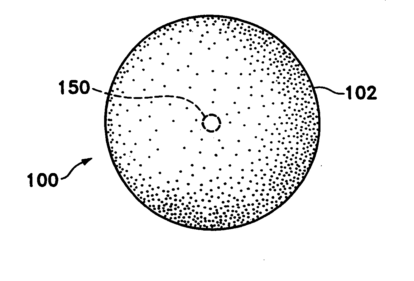
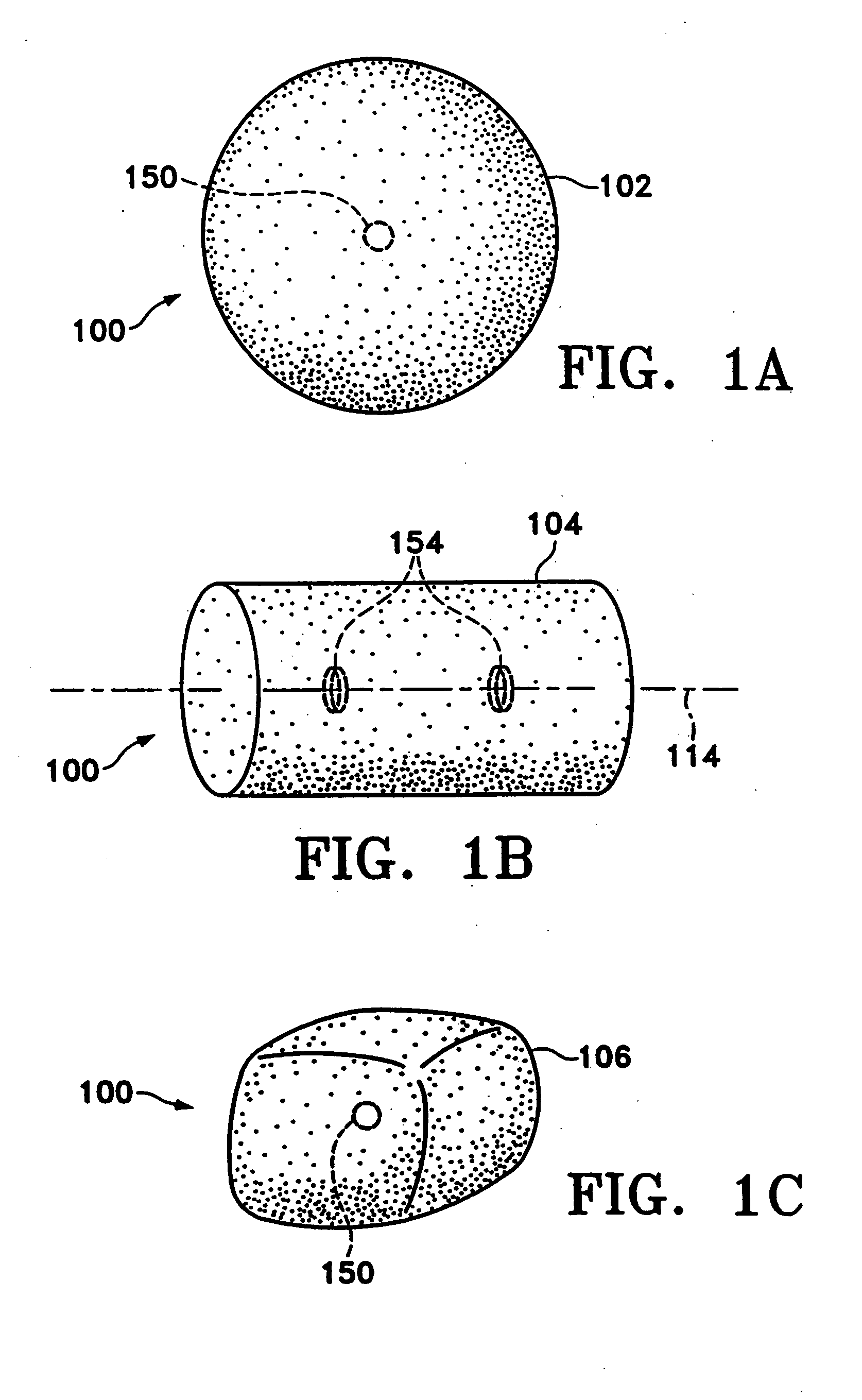
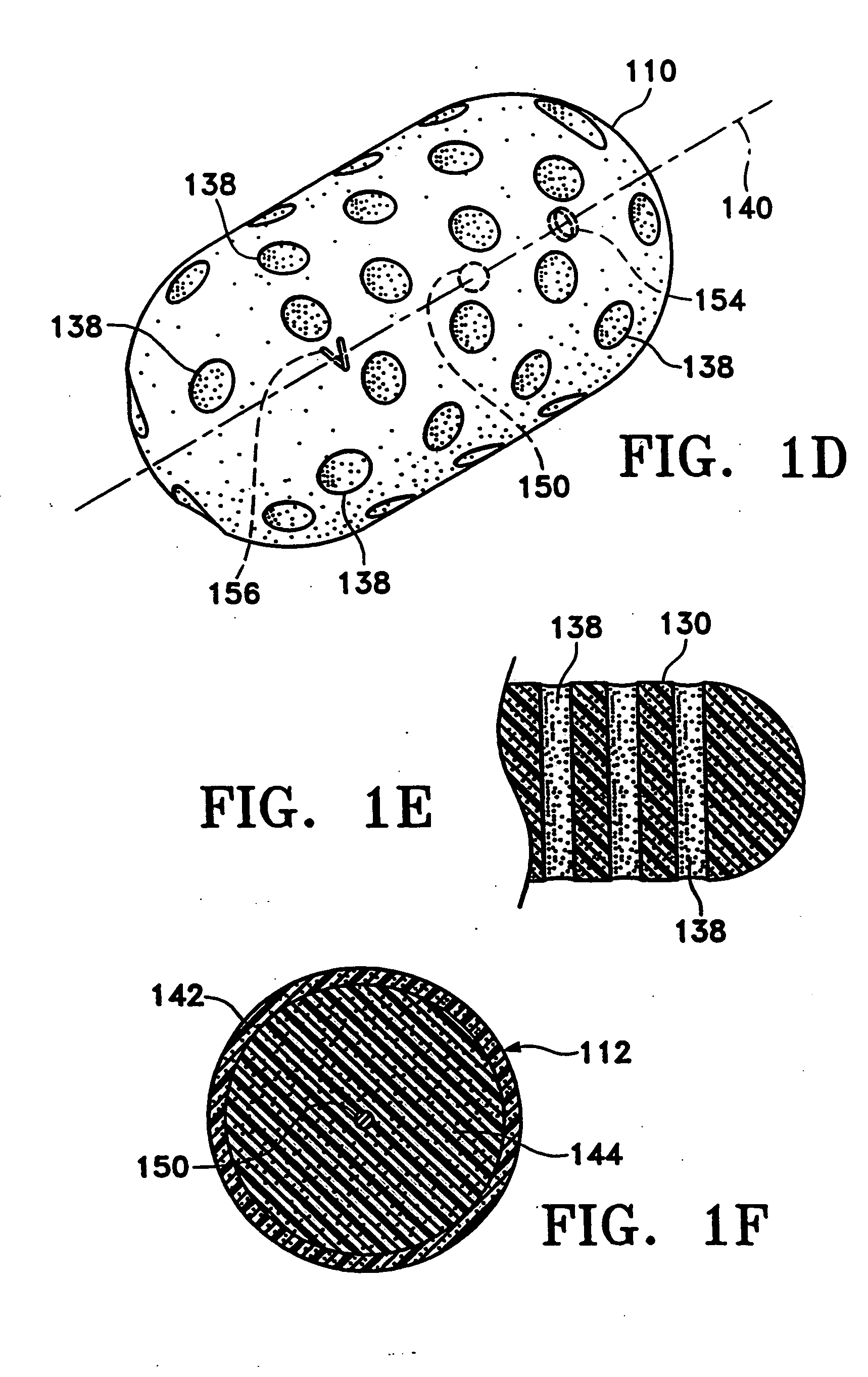
[0047]FIGS. 1A-1C show various configurations of a preferred subcutaneous cavity marking device of the present invention. Here the marking device (100) is displayed as having either a generally spherical body (102) (FIG. 1A), a generally cylindrical body (104) (FIG. 11B), or a multi-faced or irregular body (106) (FIG. 1C). In general, it is within the scope of this invention for the body to assume a variety of shapes. For example, the body may be constructed to have substantially curved surfaces, such as the preferred spherical (102) and cylindrical (104) bodies of FIGS. 1A and 1B, respectively. The body may have conical or ellipsoidal, etc., shapes as well. It is further within the scope of this invention for the body to have substantially planar surfaces, such as polyhedric (i.e., cubic, tetrahedral, etc.) or prismatic, etc., forms. Finally, the body may also have an irregular or random shape, in the case of a gel, combining features of various curved and planar surfaces. Body (10...


PUM

PropertyMeasurementUnit
resilientaaaaaaaaaa
radiopaqueaaaaaaaaaa
frequencyaaaaaaaaaa

Abstract

These are biopsy site marking devices. More particularly, the devices include a body of gelatin and an x-ray detectable body of a specific, predetermined non-biological configuration embedded in the body of gelatin. In one embodiment, the x-ray detectable body is made from metal. In alternative embodiments, the x-ray detectable body can be made from stainless steel or metal oxides.

Description

[0001] This is a continuation of U.S. application Ser. No. 10 / 114,712, filed Apr. 1, 2002, which is a continuation of U.S. application Ser. No. 09 / 805,652, filed Mar. 13, 2001, which is a continuation of U.S. application Ser. No. 09 / 285,329, filed Apr. 2, 1999, now U.S. Pat. No. 6,356,782, which is a continuation-in-part of U.S. application Ser. No. 09 / 220,618, filed Dec. 24, 1998, now abandoned. All of the above patents and applications are incorporated herein by reference in their entirety.FIELD OF THE INVENTION [0002] This invention is directed to subcutaneous cavity marking devices and methods. More particularly, a cavity marking device and method is disclosed that enable one to determine the location, orientation, and periphery of the cavity by radiographic, mammographic, echographic, or other non-invasive techniques. The invention typically is made up of one or more resilient bodies and a radiopaque or echogenic marker. BACKGROUND OF THE INVENTION [0003] Over 1.1 million breas...

Claims


Application Information

Patent Timeline
Patent Type & Authority Applications(United States)
IPC IPC(8): A61B19/00A61K49/00
CPCA61B19/54A61B2019/5408A61B8/481A61K49/006A61K49/222A61B2019/5487A61B90/39A61B2090/3908A61B2090/3987
Inventor SIRIMANNE, D. LAKSENSUTTON, DOUGLAS S.FAWZI, NATALIE V.LEBOVIC, GAIL
Owner DEVICOR MEDICAL PROD
Learn More