
Pocket tool

Active Publication Date: 2005-04-21
VICTORINOX
View PDF7 Cites 58 Cited by
  • Summary
  • Abstract
  • Description
  • Claims
  • Application Information

AI Technical Summary

Benefits of technology

[0010] The present invention is based on the problem to extend the range of application of a pocket tool without influencing thereby the dimensions of the pocket tool as such. A part problem of the present invention consists in expanding the scope of functions and the range of application of the pocket tool with respect to its capability of processing digital data, the objective being to maintain the mechanical functionality through the availability of tools and utensils.
[0011] The problem of the invention is resolved by the features defined in the characterizing clause of claim 1. The benefits resulting from said features include that the second functional component in the form of an electronic module can be moved for its application into a position outside of the receiving range of the pocket tool, achieving in this manner superior accessibility particularly to the interface. In the nonvolatile storage, it is possible to write in and read out data, for example text data or data as video and language information and the like, and programs, e.g. application programs and the like, whereby the nonvolatile storage is wherein contrary to the known volatile main memories, where data and programs can be read in and written out as well, the electrical energy supply can be dispensed with, and the space volume otherwise required for accommodating, e. g. a battery in the housing, can be used either as an additional storage space or for additional tools. The functionality of the pocket tools, and in particular the memory capacity or the range of application as a tool can be significantly raised in this way without substantially increasing its outside dimensions. It is advantageous also that a releasable locking device is arranged between the functional component and the housing, because any unintentional removal of the functional component from its storage position, for example, is excluded to the greatest possible extent. The longitudinal guide or pivot-mount between the support casing of the second functional component, and the housing of the pocket tool effect a smooth movement of the second functional component vis-à-vis the receiving area or a bearing axle arranged in the housing.
[0012] The embodiment according to claim 2 and 47 is advantageous in that, on the one hand, the memory and the control circuit and / or the at least one peripheral are arranged within the support casing, which is enclosed on all sides and consequently protected from environmental influences such as, e.g. moisture, dust and the like; and that the support casing has high mechanical stability and is insensitive to pressure stress, on the other hand. The interface represents a link between the memory and an external EDP system.

Problems solved by technology

If the memory is designed as a ROM memory, data can only by read out from the memory; however, no data can be written into the memory, which means the user can exclusively utilize the data or programs preset by the manufacturer of the pocket tool, which highly restricts the field of application of such a pocket tool.
Such a multifunctional tool does in fact extend the functionality of a pocket knife or manual tool; however, the scope of functions is exclusively limited to the processing of detectable measured physical values.
The pocket tools known from the prior art are generally found to be lacking with respect to their capability of processing digital data and outputting the latter in a form the user can detect, so there is a demand for additionally extending the scope of functions of pocket tools, while maintaining at the same time in the usual manner the scope of functions to which the user is accustomed to, such functions being achievable with functional tools or components such as, e.g. screwdrivers, knifes, scissors, and utensils such as, e.g. toothpicks etc.

Method used


Image

  • Pocket tool
  • Pocket tool
  • Pocket tool

Examples


Embodiment Construction

[0075] It is noted herewith by way of introduction that in the different embodiments described herein, identical components are provided with identical reference numerals and identical component drawings, and that the disclosure contained throughout the specification can be applied in the same sense to identical reference numerals and identical component drawings. Furthermore, data relating to positions such as, e.g. top, bottom, laterally etc. relate to the directly described and shown figures, and have to be applied in the same sense to the new position where a position has changed. Moreover, individual features or combinations of features in the different exemplified embodiments shown and described herein may per se represent independent inventive solutions, and solutions as defined by the invention.

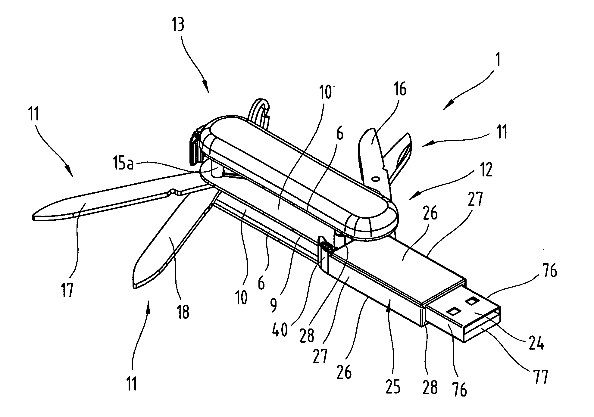
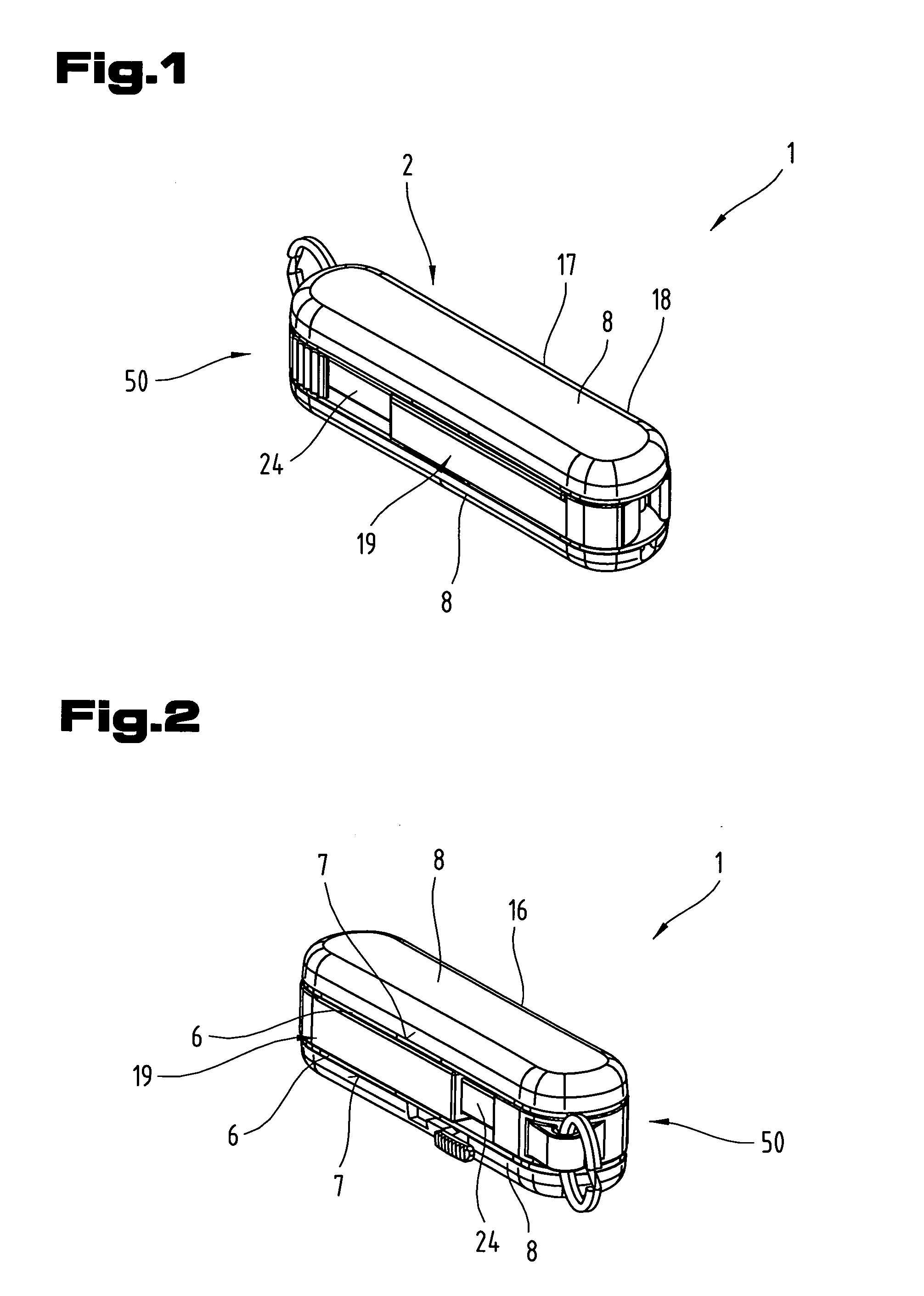
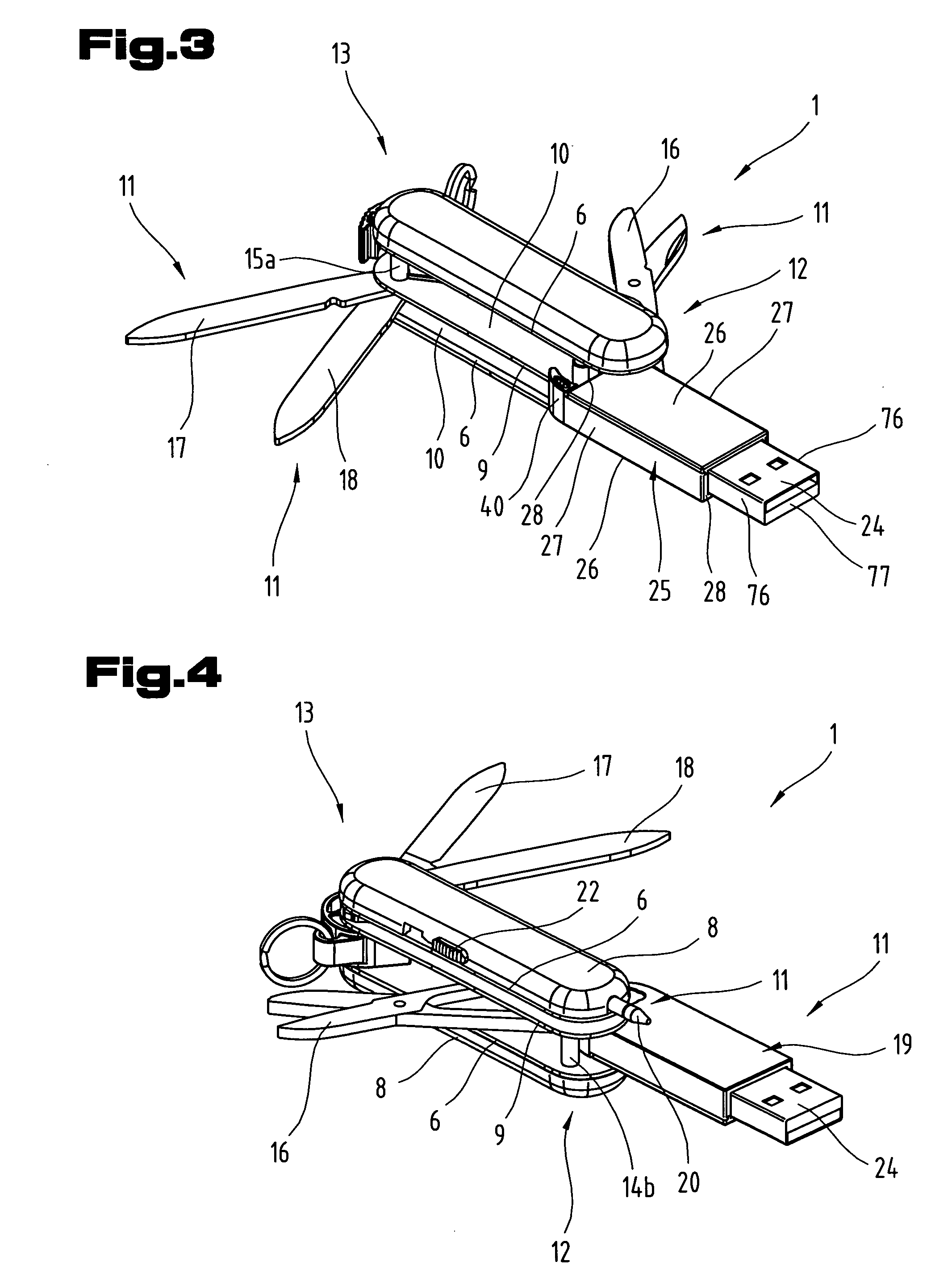
[0076] The jointly described FIGS. 1 to 15 show a first design variation of the pocket tool as defined by the invention. According to said variation, the pocket tool is formed by a p...


PUM


Abstract

The invention specifies a pocket tool, particularly a pocket knife (1) or plate-like tool card, comprising a housing (2) with at least one receiving area (10), and at least two functional components (11) movable from a storage position within the receiving area (10), into a working position outside of the receiving area (10). The first functional component (11) is designed as a tool, particularly a pair of scissors (16) or knife (1). The second functional component (11) has a support casing (25) and is equipped with a recordable and readable, nonvolatile memory, as well as with an interface (24). A releasable locking device and a longitudinal guide or pivot bearing are arranged between the support casing (25) of the second functional component (11) and the housing (2).

Description

CROSS REFERENCE TO RELATED APPLICATIONS [0001] Applicant claims priority under 35 U.S.C. §119 of AUSTRIAN Patent Application No. A 1650 / 2003 filed on Oct. 17, 2003. BACKGROUND OF THE INVENTION [0002] 1. Field of the Invention [0003] The invention relates to a pocket tool as defined in the introductory parts of claims 1 and 44. Furthermore, it relates to a functional component as defined in the introductory part of claim 116. [0004] 2. The Prior Art [0005] Different designs of pocket tools in the form of pocket knifes or plate-shaped tool cards are known from WO 01 / 39629 A1 and CH 686 173 A5. Such tools comprise a housing with at least one receiving area and a number of functional components that are movable from a storage position within the receiving area, to a working position outside of the receiving area. On the one hand, such functional components are formed by tools such as, for example a pair of scissors, a knife, a screwdriver and the like, and by utensils such as, for examp...

Claims


Application Information

Patent Timeline
IPC IPC(8): A61C15/02B25F1/04B26B1/04B26B11/00B26B13/22G06K19/04
CPCA61C15/02B25F1/04B26B1/04G06K19/07732B26B11/008B26B13/22G06K19/04B26B11/001B25H3/02B26B11/00
Inventor ELSENER, CARL
Owner VICTORINOX
Features
  • Generate Ideas
  • Intellectual Property
  • Life Sciences
  • Materials
  • Tech Scout
  • Unparalleled Data Quality
  • Higher Quality Content
  • 60% Fewer Hallucinations
Learn More