Rotating barbecue grill

a grill and rotating technology, applied in the field of barbecue grills, can solve problems such as lack of comfortability, and achieve the effect of minimizing the consumption of charcoal or gas and minimizing the excessive burning of food

Inactive Publication Date: 2005-04-21
YOON CHEOL JUNG
View PDF17 Cites 12 Cited by
  • Summary
  • Abstract
  • Description
  • Claims
  • Application Information

AI Technical Summary

Benefits of technology

[0005] The present invention is contrived to overcome the conventional disadvantages. Accordingly, an object of the invention is to provide a barbecue grill that realizes an even br

Problems solved by technology

A problem in the above disclosure is an instability

Method used


Image

  • Rotating barbecue grill
  • Rotating barbecue grill
  • Rotating barbecue grill

Examples


Embodiment Construction

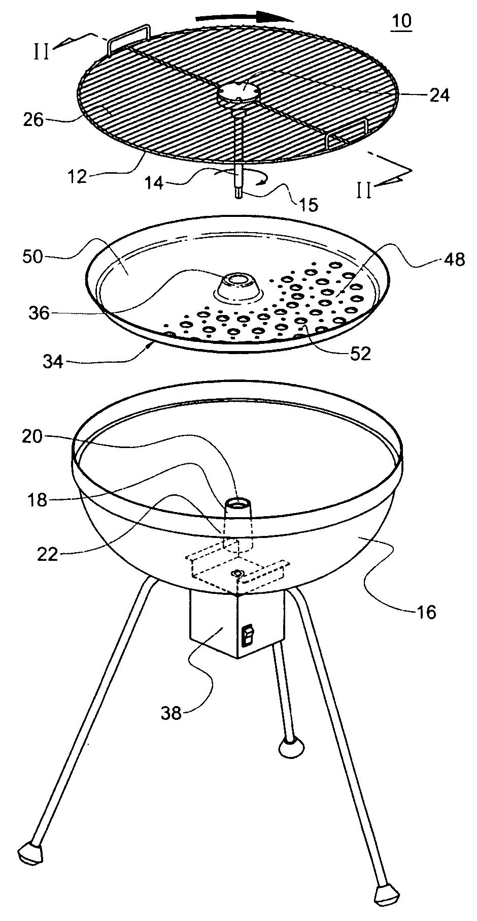
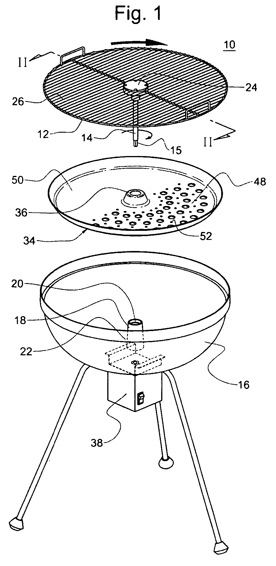
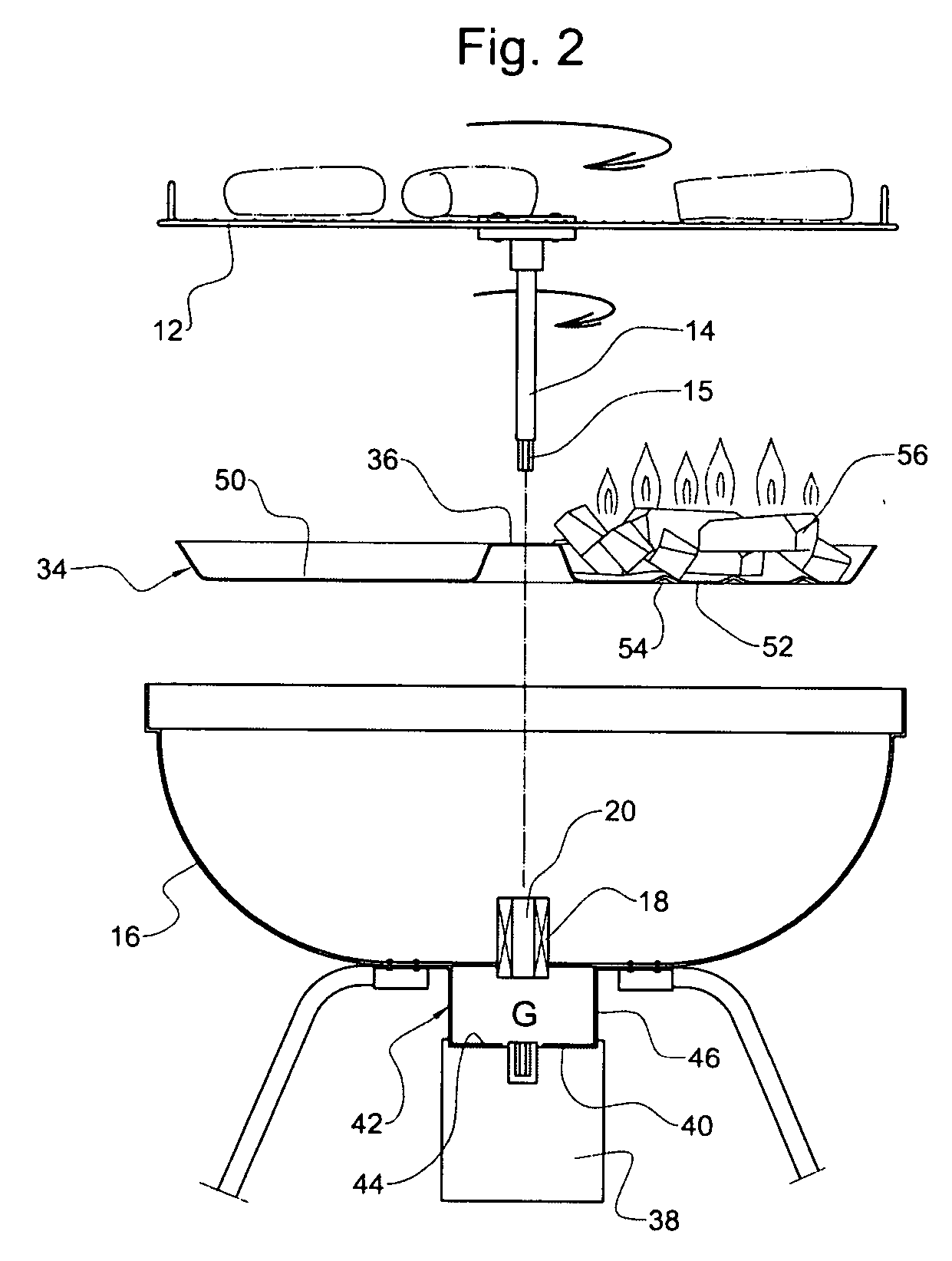
[0019]FIG. 1 shows an assembly view of a barbecue grill 10 according to the present invention in a vertically exploded alignment, FIG. 2 shows a mechanism of the grill operation in relation with FIG. 1, and FIG. 3 shows a partially sectioned view of the barbecue grill 10. As shown therein, the barbecue grill 10 includes a gridiron disk 12, and a shaft 14. The shaft 14 extends from the gridiron disk 12 so that the shaft 14 becomes substantially perpendicular to the gridiron disk 12. In a preferred version, the shaft 14 is either fixed to the gridiron disk 12 or detachably attached to the gridiron disk 12. Preferably, the shaft 14 is attached to a center portion 24 of the gridiron disk.

[0020] As further shown in FIGS. 4 and 5, the gridiron disk 12 may be either radially embossed or marginally stepped to provide convenience in food arrangement and further control of food broiling on the gridiron disk 12. Also, FIGS. 6 and 7 show variations of wire alignment for the gridiron disk 12. T...


PUM


Abstract

A barbecue grill comprises a gridiron disk, a shaft extending from the gridiron disk so that the shaft becomes substantially perpendicular to the gridiron disk, a bowl having a channel where the shaft is detachably received through the channel, and a motor attached to the bowl to generate rotation of the shaft.

Description

BACKGROUND OF THE INVENTION [0001] This invention relates to a barbecue grill. More particularly, the present invention relates to a barbecue grill having a rotating gridiron disk to realize an even broiling and a minimal food burning with less consumption of charcoal or gas. [0002] Conventional charcoal grills on the market are provided with an iron bowl to hold charcoals and a grill plate grated with wires. The grill plate is hooked above the charcoals and supported by an upper portion of the iron bowl. In order to evenly barbecue on the grill plate, the ham or equivalents need to shift from center to edge or edge to center, or to flip over when required. In order to use the typical outdoor grill, food is placed on a fixed grill surface, and a source of heat is provided. [0003] U.S. Pat. No. 6,564,793 discloses rotation of a heat source or a firebox using a shaft connected to the firebox. The firebox rotation is urged by a motor and serves to decrease unexpected flaring from the h...

Claims


Application Information

Patent Timeline
IPC IPC(8): A47J37/04A47J37/07F24B3/00
CPCA47J37/043A47J37/0745A47J37/0704
Inventor YOON, CHEOL JUNG
Owner YOON CHEOL JUNG
Why Eureka
Try Eureka