
Automatically-activated wireless hand-supportable laser scanning bar code symbol reading system with data transmission activation switch and automatic communication range dependent control

a technology of automatic activation switch and bar code symbol reading system, which is applied in the direction of instruments, sensing record carriers, sensing by electromagnetic radiation, etc., can solve the problems of reducing worker productivity, difficult to achieve in practice, and wasting valuable time and resources of users

Inactive Publication Date: 2005-04-21
METROLOGIC INSTR
View PDF99 Cites 41 Cited by
  • Summary
  • Abstract
  • Description
  • Claims
  • Application Information

AI Technical Summary

Benefits of technology

[0016] Another object of the present invention is to provide a wireless automatically-activated laser scanning bar code symbol reading system and method which provides the user with a greater degree of control over the disposition of bar code symbol reading processes automatically initiated to read bar code symbols printed on diverse types of objects including, but not limited to, printed bar code symbol menus.
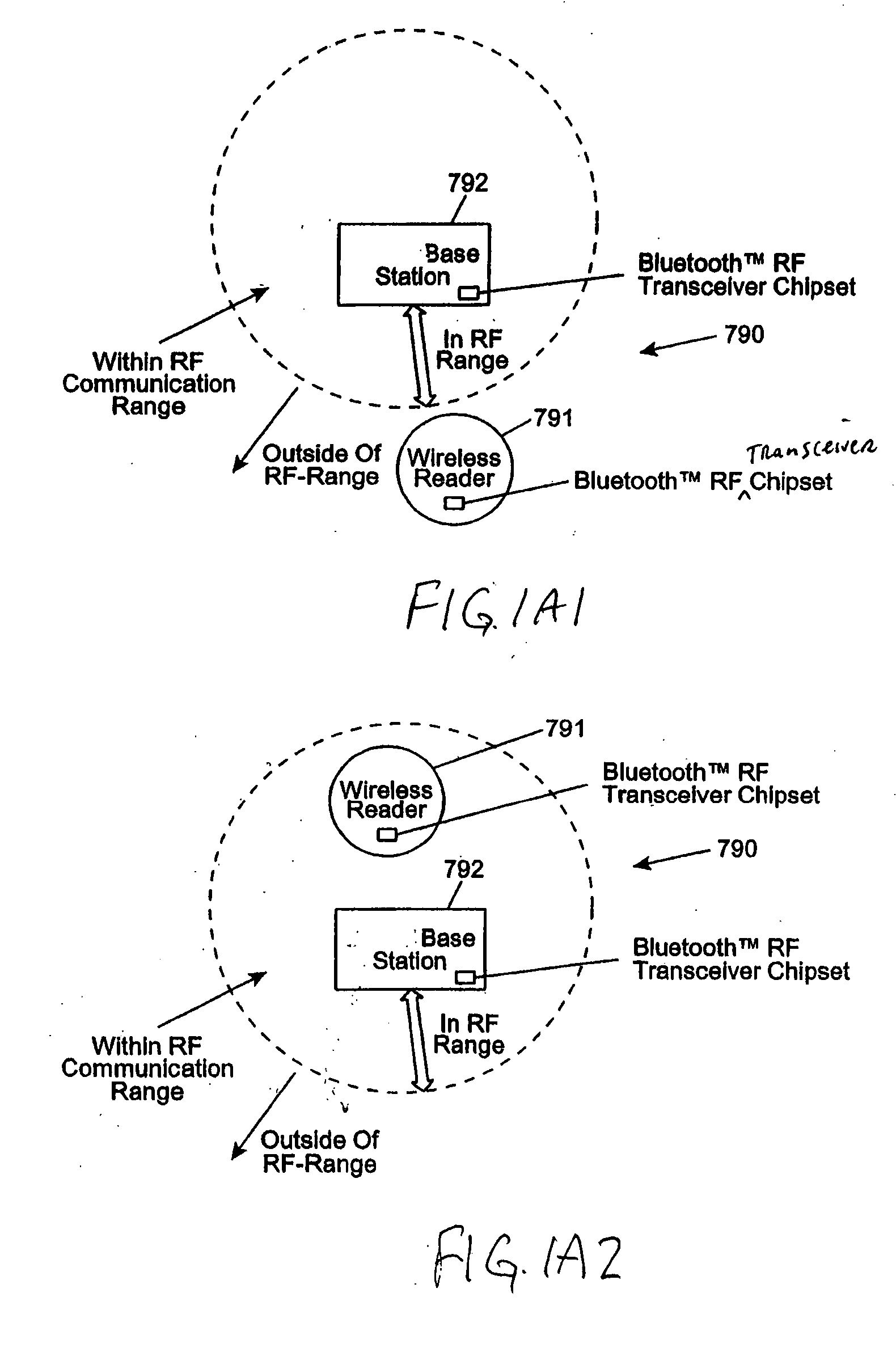
[0046] A further object of the present invention is to provide a wireless bar code symbol reading system capable of automatically collecting and storing symbol character data when hand-supportable unit is operated outside of its RF data communication range, and automatically transmitting stored symbol character data when the hand-supportable unit is operated within its RF data communication range.

Problems solved by technology

Oftentimes inadvertent bar code symbol reading errors must be corrected at their time of occurrence, wasting valuable time and resources of the user.
However, even when using this short-range CCD emulation mode, it is possible for the automatically-generated laser scanning pattern to inadvertently read an undesired bar code from the bar code menu as the operator moves the head portion of the hand-held reader into position over the bar code symbol to be read.
While it is possible in theory to operate the IR-based object detector in a short-range mode of operation, cost considerations make this difficult to achieve in practice.
Until steps are taken to reconfigure the bar code symbol reader into its long range mode of operation, the user is forced to read bar code symbols in its CCD-emulsion mode which can be inconvenient in many types of scanning applications, thus reducing worker productivity.
When using the above-described system to read bar code symbols on products that have been placed among a set of previously “scanned” products at a check-out counter, there is a high likelihood that previously scanned products will be accidentally re-read, creating an error in check-out operations.
In wireless portable bar code symbol reading apparatus, the above problems are further exacerbated because of the need of the consumer battery power.

Method used


Image

  • Automatically-activated wireless hand-supportable laser scanning bar code symbol reading system with data transmission activation switch and automatic communication range dependent control
  • Automatically-activated wireless hand-supportable laser scanning bar code symbol reading system with data transmission activation switch and automatic communication range dependent control
  • Automatically-activated wireless hand-supportable laser scanning bar code symbol reading system with data transmission activation switch and automatic communication range dependent control

Examples


Embodiment Construction

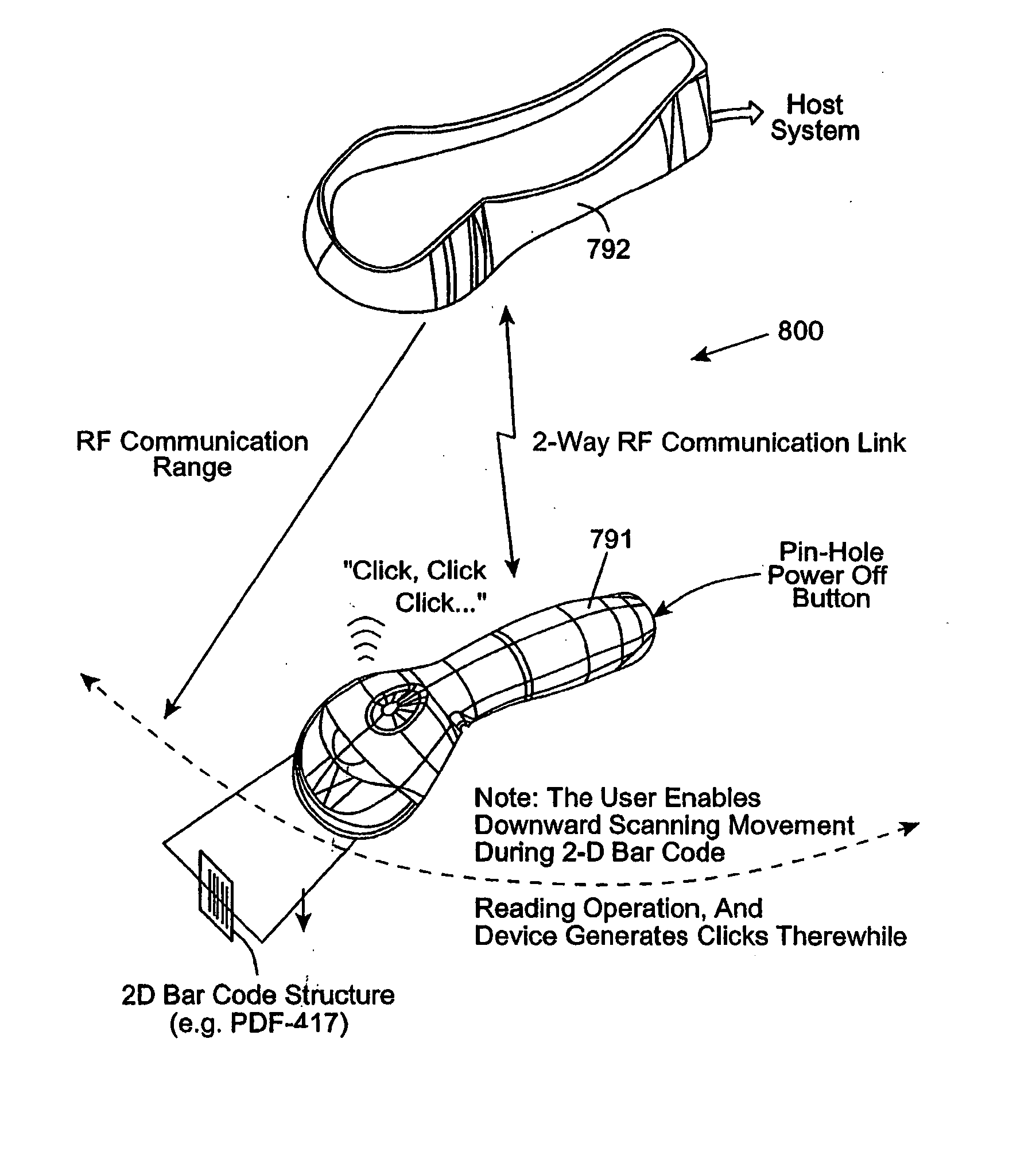
[0119] Referring to the figures in the accompanying Drawings, the various illustrative embodiments of the wireless automatically-activated laser scanning bar code symbol reading system of the present invention will be described in great detail, wherein like elements will be indicated using like reference numerals.

[0120] Prior to detailing the various illustrative embodiments of the present invention, it will be helpful to first provide a brief overview of the system and method thereof.

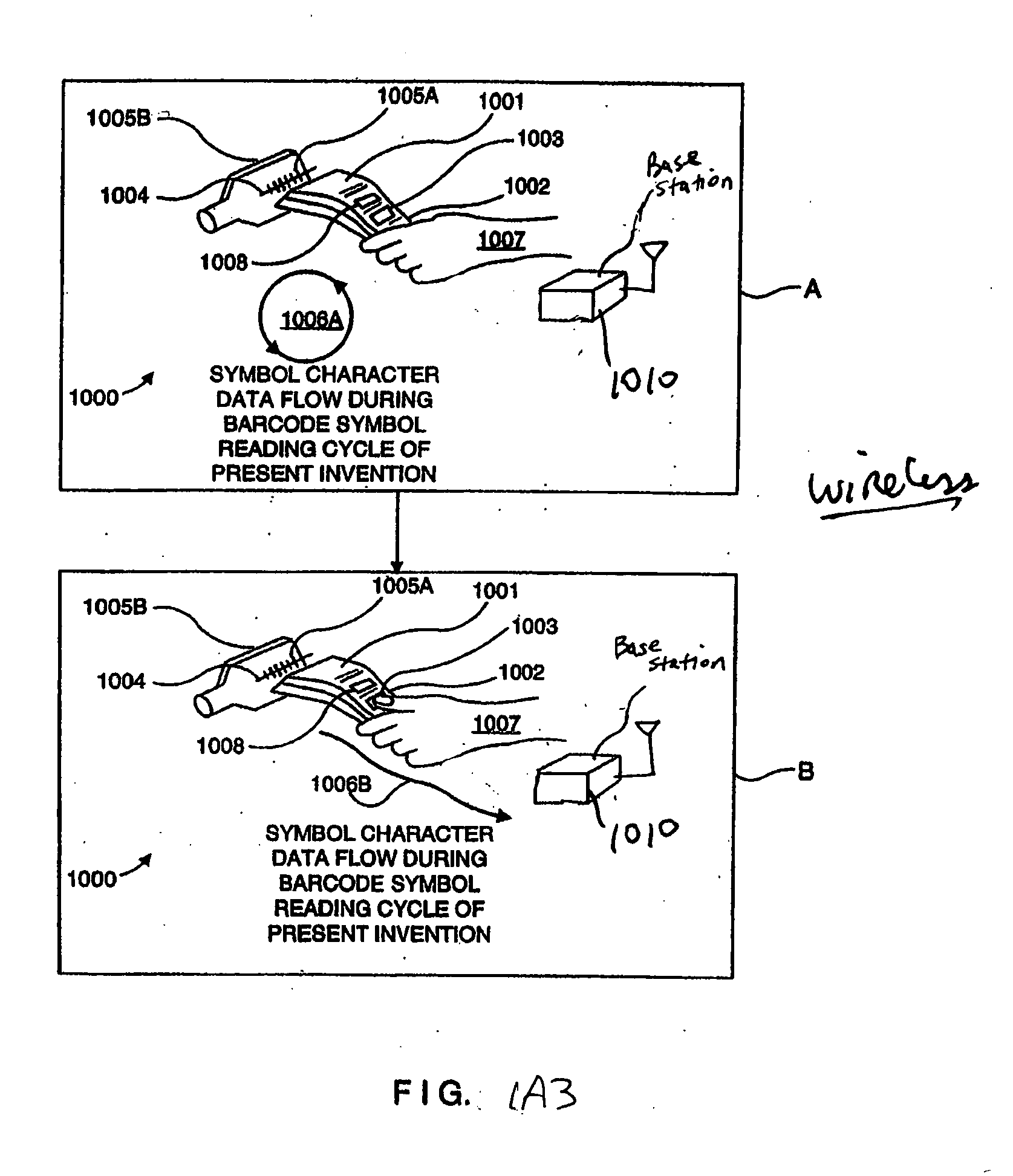
[0121] As illustrated in FIGS. 1A1 and 1A2, the wireless automatically-activated bar code symbol reading system 1000 of the present invention generally comprises: a hand-supportable bar code symbol reader 1001 having a bar code symbol reading mechanism and a Bluetooth® RF-based transceiver chipset 803 contained within a hand-supportable housing 1002 having a manually-activatable data transmission switch 1008; and base station 1010 also having Bluetooth® RF-based transceiver chipset 804 contained with...


PUM


Abstract

An automatically-activated wireless code symbol reading system comprising a hand-supportable housing having a manually-activatable data transmission switch under automatic communication range dependent control. When a bar code symbol is read, the bar code reader is located inside the predetermined RF data communication range of the system, then the symbol character data string, produced at substantially the same time as the manual activation of the data transmission switch, is transmitted to the base station over the wireless RF communication link. If the device is outside the range, then an audible and / or visual indication is automatically generated, and the packaged symbol character data string is packaged and transmitted to a data storage buffer aboard the bar code reader. Then when the bar code symbol reader is moved within the communication range of the system, the buffered / packaged symbol character data is automatically transmitted to the base station by the RF-based data communication link.

Description

RELATED CASES [0001] The present application is a continuation-in-part (CIP) of: U.S. application Ser. No. 10 / 342,433 filed Jan. 12, 2003; U.S. application Ser. No. 10 / 611,813 filed Jul. 1, 2003; U.S. application Ser. No. 10 / 630,622 filed Jul. 30, 2003; U.S. application Ser. No. 10 / 613,774 filed Jul. 3, 2003; U.S. application Ser. No. 10 / 611,846 filed Jul. 1, 2003; U.S. application Ser. No. 10 / 613,527 filed Jul. 3, 2003; U.S. application Ser. No. 10 / 630,358 filed Jul. 30, 2003; U.S. application Ser. No. 10 / 613,758 filed Jul. 3, 2003; U.S. application Ser. No. 09 / 204,176 filed Dec. 2, 1998; U.S. application Ser. No. 09 / 452 / 976 filed Dec. 2, 1999; and International Application No. PCT / US99 / 28530, published as WIPO Publication No. WO 00 / 33239 on Jun. 8, 2000. Each said patent application is assigned to and commonly owned by Metrologic Instruments, Inc. of Blackwood, N.J., and is incorporated herein by reference in its entirety.BACKGROUND OF THE INVENTION [0002] 1. Field of the Inventio...

Claims


Application Information

Patent Timeline
Patent Type & Authority Applications(United States)
IPC IPC(8): G06K7/10G06K7/14
CPCG06K7/10G06K2207/1012G06K7/10584G06K7/10594G06K7/10603G06K7/10663G06K7/10673G06K7/10693G06K7/10702G06K7/10792G06K7/10801G06K7/10811G06K7/10851G06K7/10861G06K7/10871G06K7/10881G06K7/10891G06K7/14G06K17/0022G06K7/10564
Inventor SCHMIDT, MARKRUSSELL, GARRETTWILZ, DAVID M. SR.BLAKE, ROBERTHUDRICK, DONALD T.COLAVITO, STEPHEN J.KNOWLES, C. HARRYROCKSTEIN, GEORGEZHU, XIAOXUNBONANNO, JOHNBYUN, SUNGXU, CONGWEIJIANG, MINWANG, LINHU, MENGJIN, HONGJIANJI, MINGQINGSHI, SHAMEIAU, KA MANGIORDANO, PATRICK
Owner METROLOGIC INSTR
Learn More