Motor

a technology for motors and gear housings, applied in the field of motors, can solve the problems of increasing manufacturing costs, disadvantageous increase in gear housing size, and long assembly work, and achieve the effect of simplifying the assembly work of the motor and compact gear housing siz

Inactive Publication Date: 2005-04-21
ASMO CO LTD
View PDF20 Cites 14 Cited by
  • Summary
  • Abstract
  • Description
  • Claims
  • Application Information

AI Technical Summary

Benefits of technology

[0020] Furthermore, it is preferred that the gear housing includes a guide portion that guides the control circuit board, which is inserted in the axial direction of the motor unit, to a predetermined position in the gear housing. With this construction, the control circuit board is positioned relative to the gear housing, so that assembly of the control circuit board to the gear housing can be more easily accomplished.
[0021] Furthermore, in the first to fourth inventions, it is preferred that the motor unit includes a rotatable shaft; the speed reducing unit includes a worm shaft, which is coaxial with the rotatable shaft and is provided separately from the rotatable shaft; and the rotatable shaft of the motor unit and the worm shaft of the speed reducing unit are integrally rotatably coupled when the motor unit is assembled with and is connected to the speed reducing unit. Therefore, in the motor, which has the rotatable shaft and the worm shaft that are integrally rotatably coupled upon assembling and connecting of the motor unit with the speed reducing unit, it is possible to achieve the compact size of the gear housing of the speed reducing unit and also to simplify assembly work of the motor.

Problems solved by technology

However, in the arrangement 1, a receiver, which receives the control circuit board, is formed integrally in the gear housing, so that a size of the gear housing is disadvantageously increased.
Furthermore, the gear housing, which has the receiver for receiving the control circuit board, is not interchangeable with a gear housing of another type of motor, which does not integrally include the control circuit board, i.e., a gear housing of a normal type motor.
Thus, versatility of the gear housing cannot be achieved, disadvantageously resulting in an increase in the manufacturing costs.
Thus, the entire assembly work disadvantageously becomes lengthy.

Method used


Image

  • Motor
  • Motor
  • Motor

Examples


first embodiment

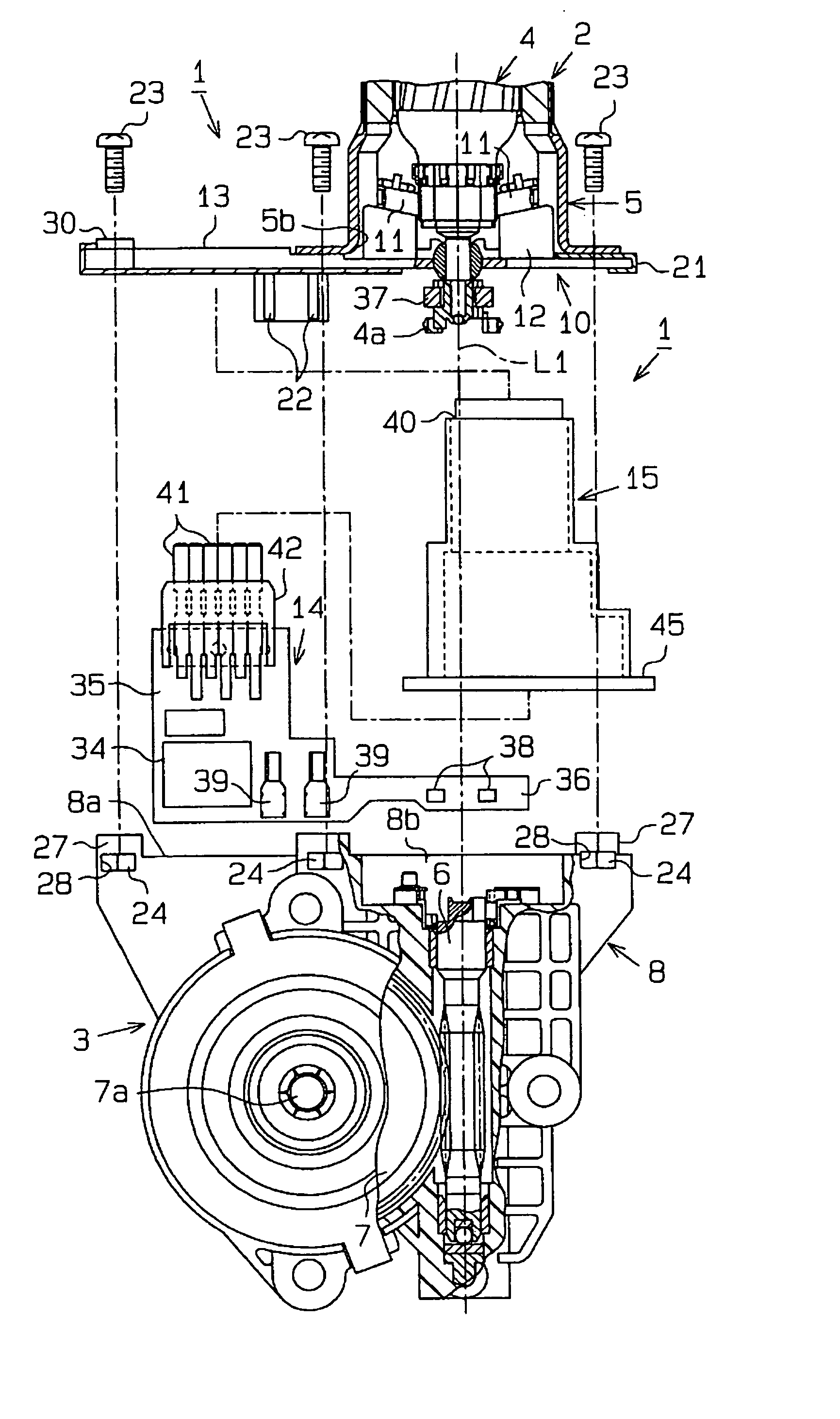
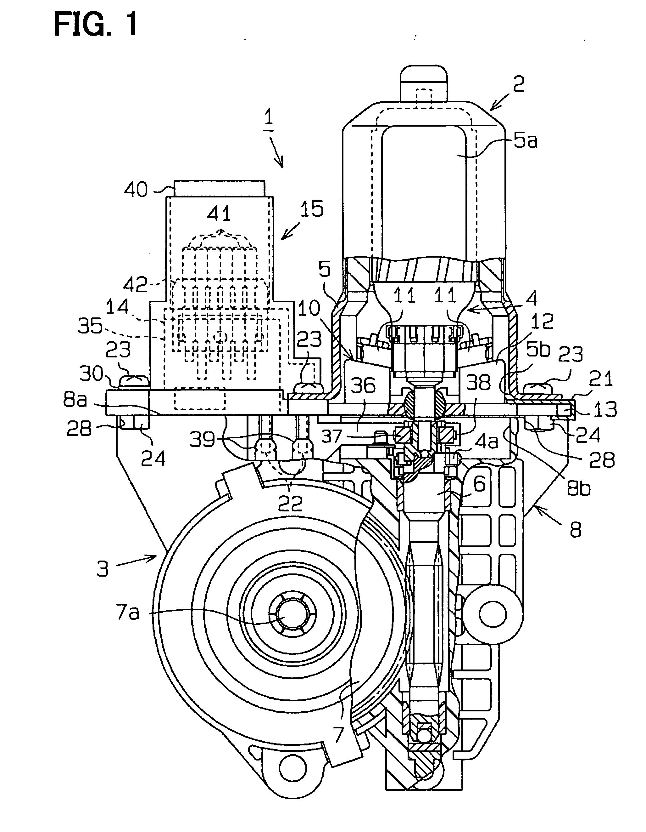
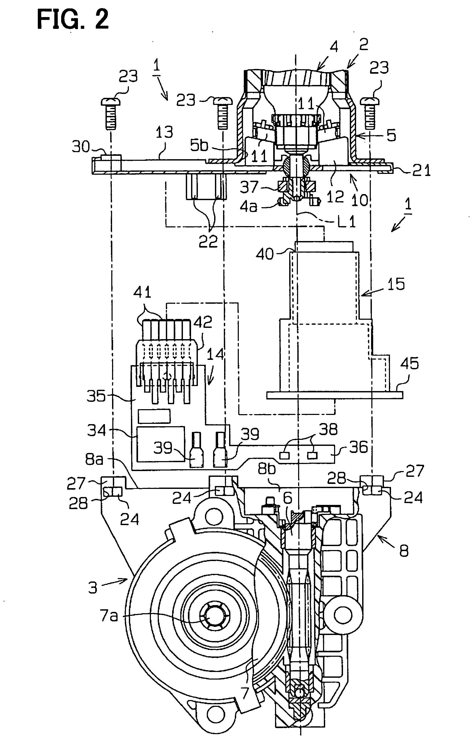
[0023] A first embodiment, in which the present invention is implemented in a motor that serves as a drive source of a vehicle power window system, will be described with reference to FIGS. 1 to 3. FIG. 1 is a partially fragmented schematic front view of the motor, and FIG. 2 is a partially fragmented deployed front view of the motor.

[0024] As shown in FIGS. 1 and 2, the motor 1 includes a motor unit 2 and a speed reducing unit 3, which decelerates rotation of the motor unit 2. The motor unit 2 has a metal yoke (a yoke housing) 5, which rotatably receives an armature 4. The yoke 5 is flat and has a pair of flat portions 5a, which are parallel to one another (FIG. 1). The speed reducing unit 3 includes a resin gear housing 8, which rotatably receives a worm shaft 6 and a worm wheel 7. The worm shaft 6 receives rotation of a rotatable shaft of the armature 4, and the worm wheel 7 is meshed with the worm shaft 6. Rotation of the armature 4 is transmitted to the worm shaft 6 through a ...

second embodiment

[0050] Next, a second embodiment of the present invention will be described with reference to FIG. 4. The present embodiment mainly differs from the above embodiment in that the control circuit board is arranged perpendicular to the axial direction of the motor unit 2. The components similar to those discussed in the above embodiment will be indicated by the same numerals.

[0051] As shown in FIGS. 4(a) and 4(b), the end surface portion 8a of the gear housing 8 is opposed to the motor unit 2 and extends on the side opposite from the worm wheel 7. A recess 50, which is communicated with the opening 8b, is formed in the end surface portion 8a in such a manner that recess 50 extends from the opening 8b on the side opposite from the worm wheel 7 to receive a control circuit board 51. The opening 8b and the recess 50 form a receiver 52 for receiving the control circuit board 51. The control circuit board 51 has a rectangular shape and has a size that is substantially the same as that of t...


PUM


Abstract

An end surface portion 8a of a gear housing 8, which is located on a motor unit 2 side of the gear housing 8, is opposed to the motor unit 2 and laterally extends. A brush holder 10 includes a plate portion 13 that is opposed to the end surface portion 8a. A case 15, which receives the control circuit board 14, is formed separately from the plate portion 13. A receiving through hole, through which the circuit board receiver 15 is receivable, is formed in the plate portion 13. The case 15 is constructed to be positionable next to the yoke 5 in a state where the case 15 is received through the receiving through hole. The yoke 5, the gear housing 8, the brush holder 10, the control circuit board 14 and the case 15 are assembleable in a direction parallel to an axial direction of the motor unit 2. The control circuit board 14 projects from the gear housing 8 on the motor unit 2 side, and a projected part of the control circuit board 14, which projects from the gear housing 8 on the motor unit 2 side, is received in the case 15. In this way, in the motor that integrally includes the motor unit, the speed reducing unit and the control circuit board, the gear housing of the speed reducing unit can be made compact, and the assembly work can be simplified.

Description

TECHNICAL FIELD [0001] The present invention relates to a motor, more specifically to a motor, which integrally includes a motor unit, a speed reducing unit and a control circuit board. BACKGROUND ART [0002] Motors include, for example, a vehicular motor. In general, the vehicular motor includes a motor unit and a speed reducing unit, and the speed reducing unit decelerates the motor unit and is assembled integrally with the motor unit. The motor unit includes a yoke housing, which receives, for example, an armature and magnets. The speed reducing unit includes a resin gear housing, which receives a speed reducing worm mechanism that decelerates rotation transmitted from the armature one such motor is referred to as a smart type motor, which includes a control circuit board that controls rotation of the motor unit. There are various known motor arrangements, each of which includes the control circuit board. In one known arrangement (hereinafter, referred to as an arrangement 1), the...

Claims


Application Information

Patent Timeline
Patent Type & Authority Applications(United States)
IPC IPC(8): H02K5/14H02K5/22H02K7/116H02K11/04
CPCH02K5/148H02K5/225Y10S310/06H02K11/0084H02K7/1166H02K11/38H02K5/22H02K11/00
Inventor YAMAMOTO, HIROAKIIMAMURA, NAOKIMATSUYAMA, YOUICHI
Owner ASMO CO LTD
Why Eureka
Try Eureka