Pyrotechnic circuit breaker

a circuit breaker and pyrotechnic technology, applied in the direction of circuit breaker details, protective switch operating/release mechanisms, protective switch details, etc., can solve the problem of not being able to exploit the rapidity of a pyrotechnic ignition,/or the measures to focus on cutting the circuit portion are reduced, and the overall pyrotechnic output force is reduced.

Active Publication Date: 2005-04-21
DAICEL CHEM IND LTD
View PDF30 Cites 94 Cited by
  • Summary
  • Abstract
  • Description
  • Claims
  • Application Information

AI Technical Summary

Benefits of technology

[0008] In another separate and independent aspect of the invention, the portion of the circuit to be broken by the pyrotechnic igniter may be specially formed to be readily cut in response to an indirect cutting force from the pyrotechnic igniter, such as for example flattened in a plane perpendicular to the output of the pyrotechnic igniter and / or scored. Thus the overall pyrotechnic output force and / or measures to focus that force in order to cut the portion of the circuit are reduced, permitting an advantageously simplified pyrotechnic circuit breaker to be attained.

Problems solved by technology

Devices such as that of the '988 patent based on melting that is induced by conducted heat, however, cannot exploit the rapidity of a pyrotechnic ignition because the process of heat conduction is quite slow in comparison to the speed of a pyrotechnic ignition.
Such devices can also be relatively complex and costly.
Yet such devices are in general a relatively complex, costly, and / or bulky way to provide the function of pyrotechnically-induced circuit breaking.
Moreover, such devices do not intrinsically involve a conventional (i.e., current load-based) fuse, so if it were desired to also retain the conventional function of current load-based breaking in such a circuit breaker, a conventional fuse would need to be added as a distinct additional component, thus rendering the resulting device yet more complicated and costly.
The '563 patent, however, does not teach either the direct pyrotechnic ablation of any portion of a circuit, the pyrotechnically-driven cutting of a portion of the circuit that is specially formed to be readily cut, or any kind of pyrotechnically-driven breaking of a current load-based fuse in a circuit.
Thus the devices taught in the '563 patent are somewhat complicated, and none includes the function of a conventional current load-based fuse.

Method used


Image

  • Pyrotechnic circuit breaker
  • Pyrotechnic circuit breaker
  • Pyrotechnic circuit breaker

Examples


Embodiment Construction

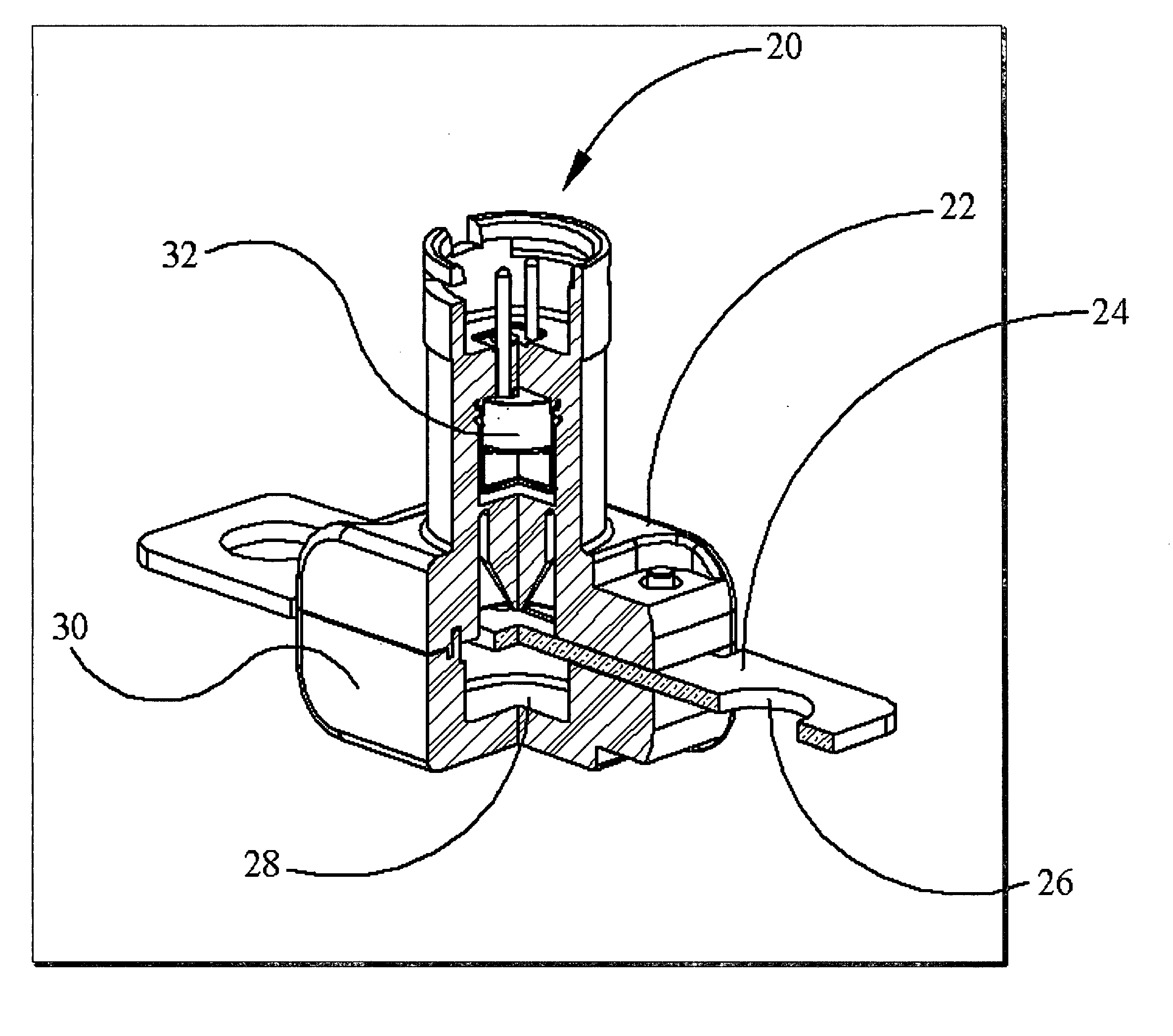
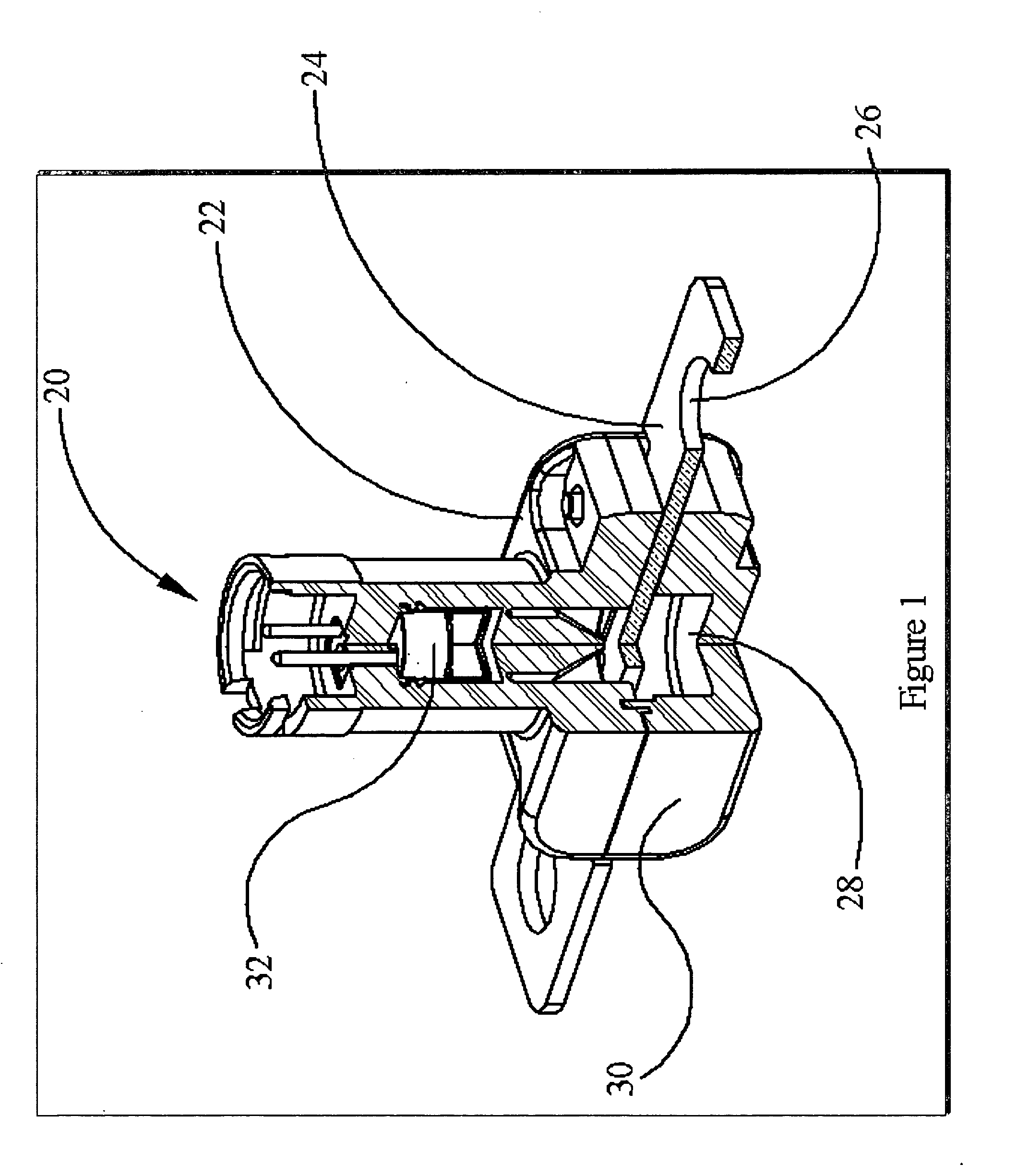
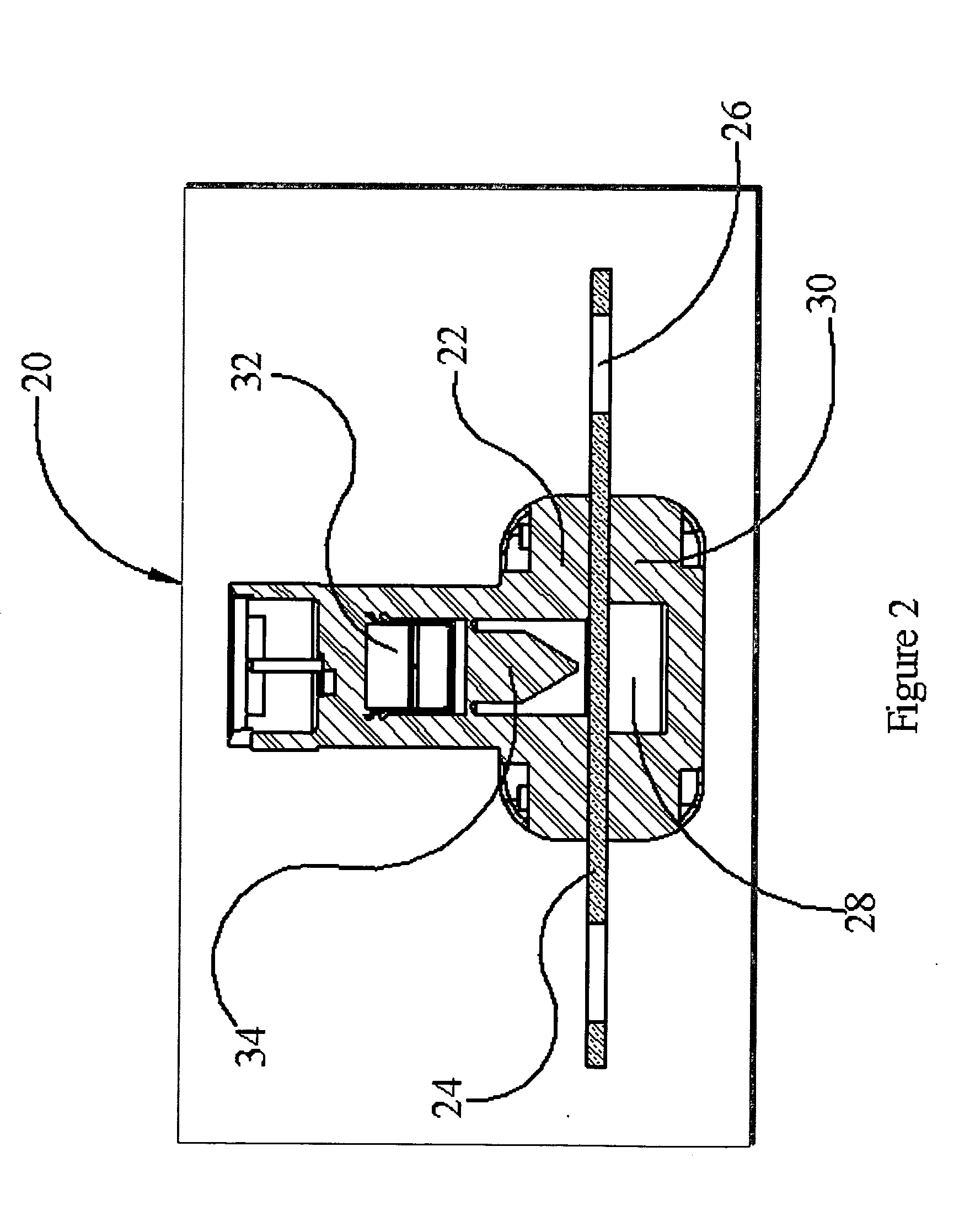
[0014] Referring to FIGS. 1 to 3, a preferred embodiment of a pyrotechnic circuit breaker 20 in accordance with the present invention may include an upper housing 22 and a lower housing 30, which may be made of metal, ceramic, or polymer, preferably a suitable high-strength, high-temperature polymer thermoplastic or thermoset such as Ryton®, Amodel®, Ultem®, Phenolic®, Zytel® and the like. The housing may preferably be constructed as an integral, one-piece, injection molded-in-place housing, preferably created by joining together two or more components. Optionally, a polymer overmolding (preferably selected for beneficial cost, formability, and electrical insulation characteristics) or a superstructure or skeleton of metal may be utilized for added strength. A pyrotechnic igniter assembly 32 is held securely within the upper housing 22, and the portion of the electrical circuit to be broken by the output of the pyrotechnic igniter assembly 32 is situated between the upper housing 22...


PUM


Abstract

A circuit breaker including a pyrotechnic element configured to ablate or cut a portion of the circuit so as to break the circuit, thereby breaking the circuit. The portion of the circuit to be broken may be specially formed to be readily ablated or cut, and/or may be a current load-based fuse.

Description

BACKGROUND OF THE INVENTION [0001] The present invention is directed generally to the field of circuit breakers, and more particularly, to a circuit breaker including a pyrotechnic element for breaking the circuit. [0002] he circuit breakers used in various electrical systems in motor vehicles such as automobiles, trucks, buses, fixed wing aircraft, helicopters, marine vessels and the like, have conventionally employed fuse-type resistor elements that burn out when an excessive level of current passes through the element, causing a break in the circuit. [0003] Various substitutes for such conventional fuses have also been devised, such as to permit breaking of a circuit in response to abnormal conditions (such as the collision of a vehicle) that would not necessarily create an immediate excessive current load in a fuse. For example, U.S. Pat. No. 6,194,988 to Yamaguchi et al. teaches the use of a sort of “hot plate” that is spring-biased against a relatively low melting point fuse s...

Claims


Application Information

Patent Timeline
Patent Type & Authority Applications(United States)
IPC IPC(8): H01H39/00H01H85/044
CPCH01H39/006H01H2085/466H01H2039/008H01H85/044B29C45/14
Inventor CARUSO, KEITH W.BONAS, ANDREW G.TIRMIZI, ABRAR A.
Owner DAICEL CHEM IND LTD
Why Eureka
Try Eureka