Light source module and lamp equipped with the same

a technology of light source module and lamp, which is applied in the direction of semiconductor devices for light sources, fixed installations, lighting and heating apparatus, etc., can solve the problems of insufficient light, limited number of led lamps that can be integrated, and difficulty in achieving vehicle lamps that output a much larger amount of light, such as headlights, and achieves simplified structure, low arrangement flexibility, and high flexibility

Inactive Publication Date: 2005-04-21
STANLEY ELECTRIC CO LTD
View PDF9 Cites 43 Cited by
  • Summary
  • Abstract
  • Description
  • Claims
  • Application Information

AI Technical Summary

Benefits of technology

[0010] The formation of a plurality of LEDs having virtual light source images and the combination of the LEDs in a ring such that they are superimposed to create a particular virtual light source image can result in a single virtual light source image that emits a radial light. This is effective to solve the conventional problems associated with low flexibility of arrangement and insufficiency of light. The invention provides, among other things, a higher flexibility than the conventional art for the number and configuration for LEDs that can be arranged.
[0011] A desirable reflected light can be achieved by positioning the virtual light source(s) at the focus of the reflecting mirror. As a result, the use of light guides may not be required and the lamp can be produced with a simplified structure that results in an improved yield and a reduced cost. In addition, a desired light distribution characteristic can be easily achieved. These possible benefits are extremely effective in improving the performance of the light.

Problems solved by technology

Accordingly, the number of LED lamps that can be integrated is limited and a problem remains in that an insufficient amount of light is produced.
For example, the conventional configuration for a lamp makes it difficult to achieve a vehicle lamp that outputs a much larger amount of light, such as a headlight.
This high level of mutual accuracy requirement for the different structures causes other problems due to complicated process steps that elevate the cost of the vehicle lamp.

Method used


Image

  • Light source module and lamp equipped with the same
  • Light source module and lamp equipped with the same
  • Light source module and lamp equipped with the same

Examples


Embodiment Construction

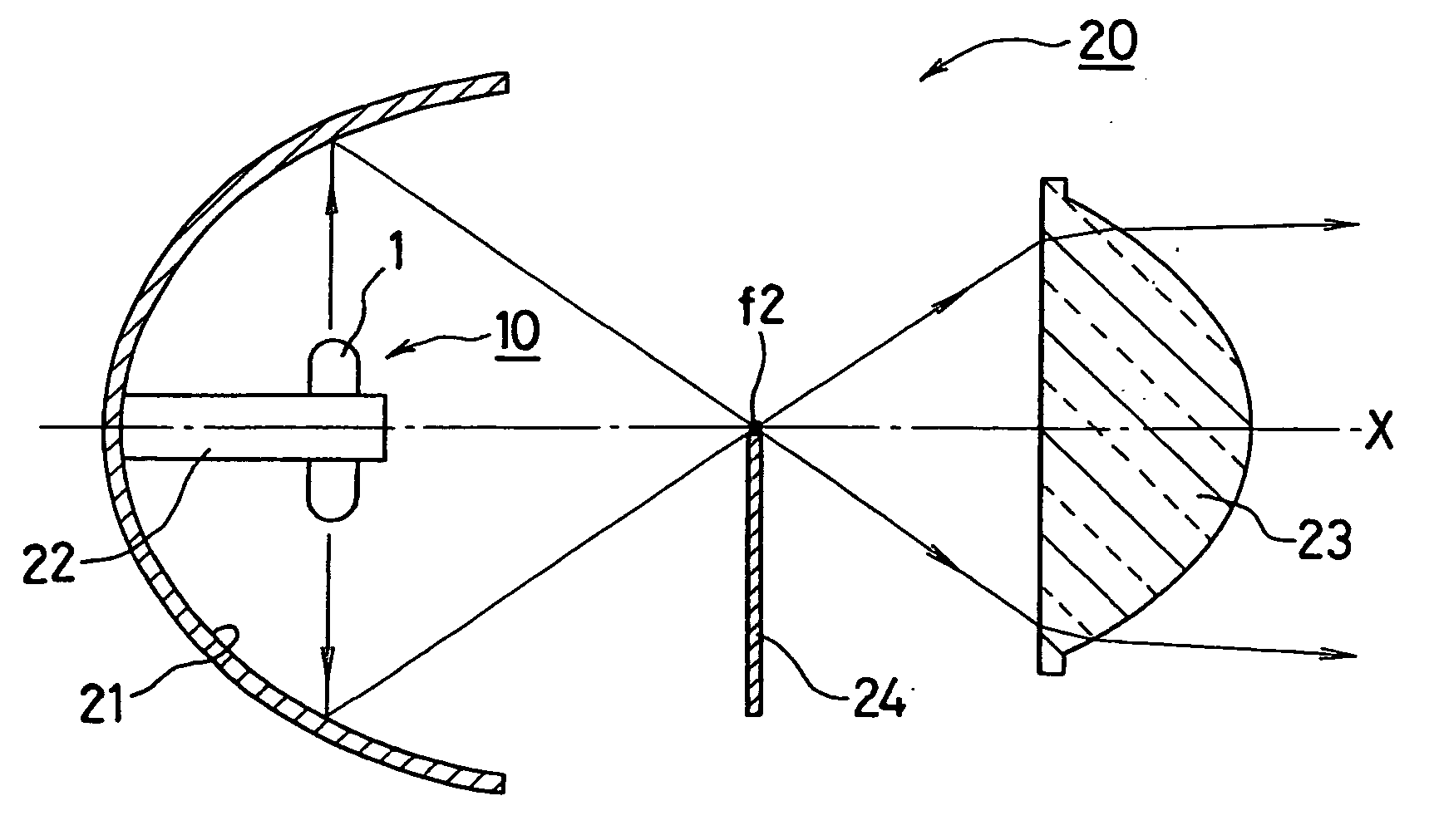
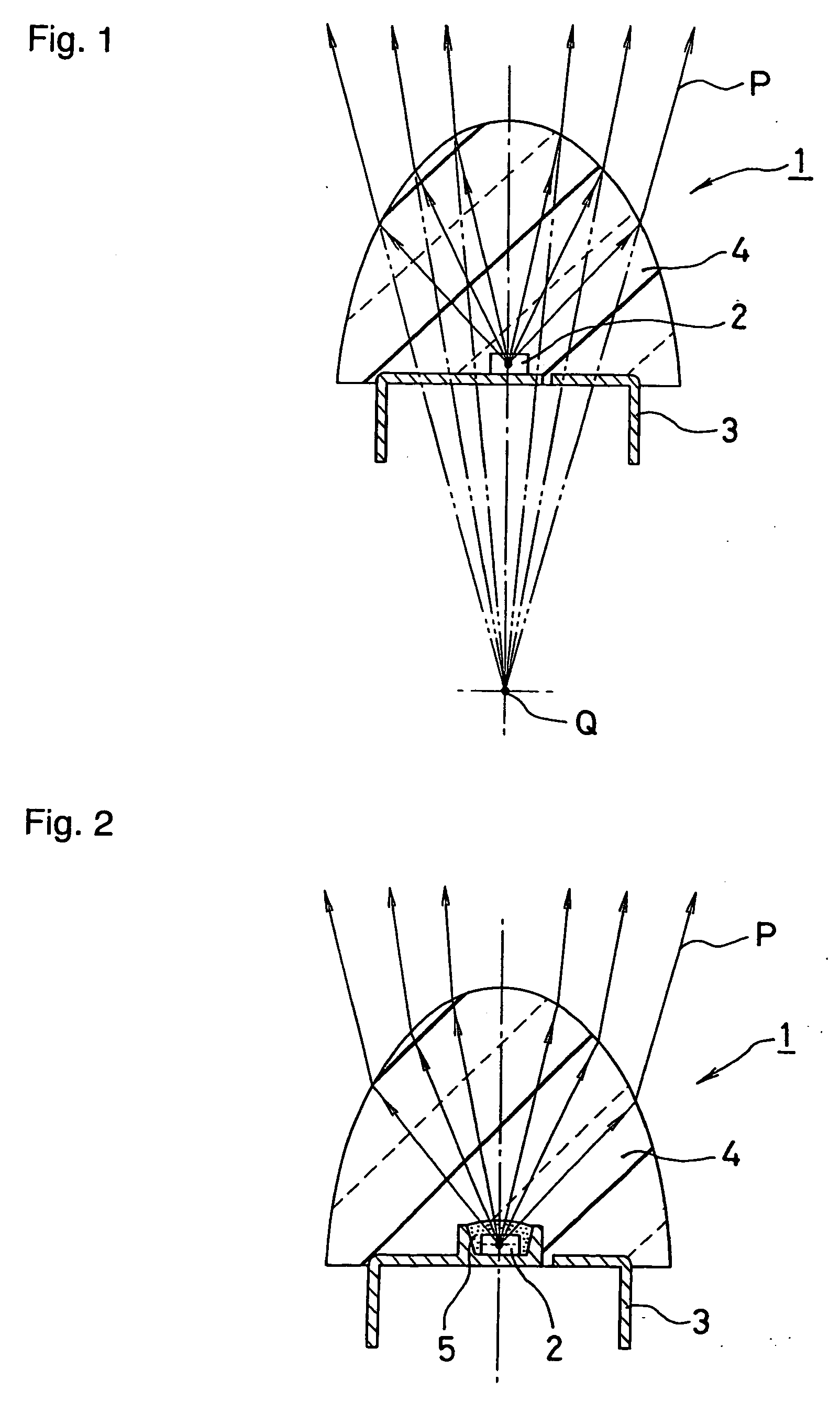
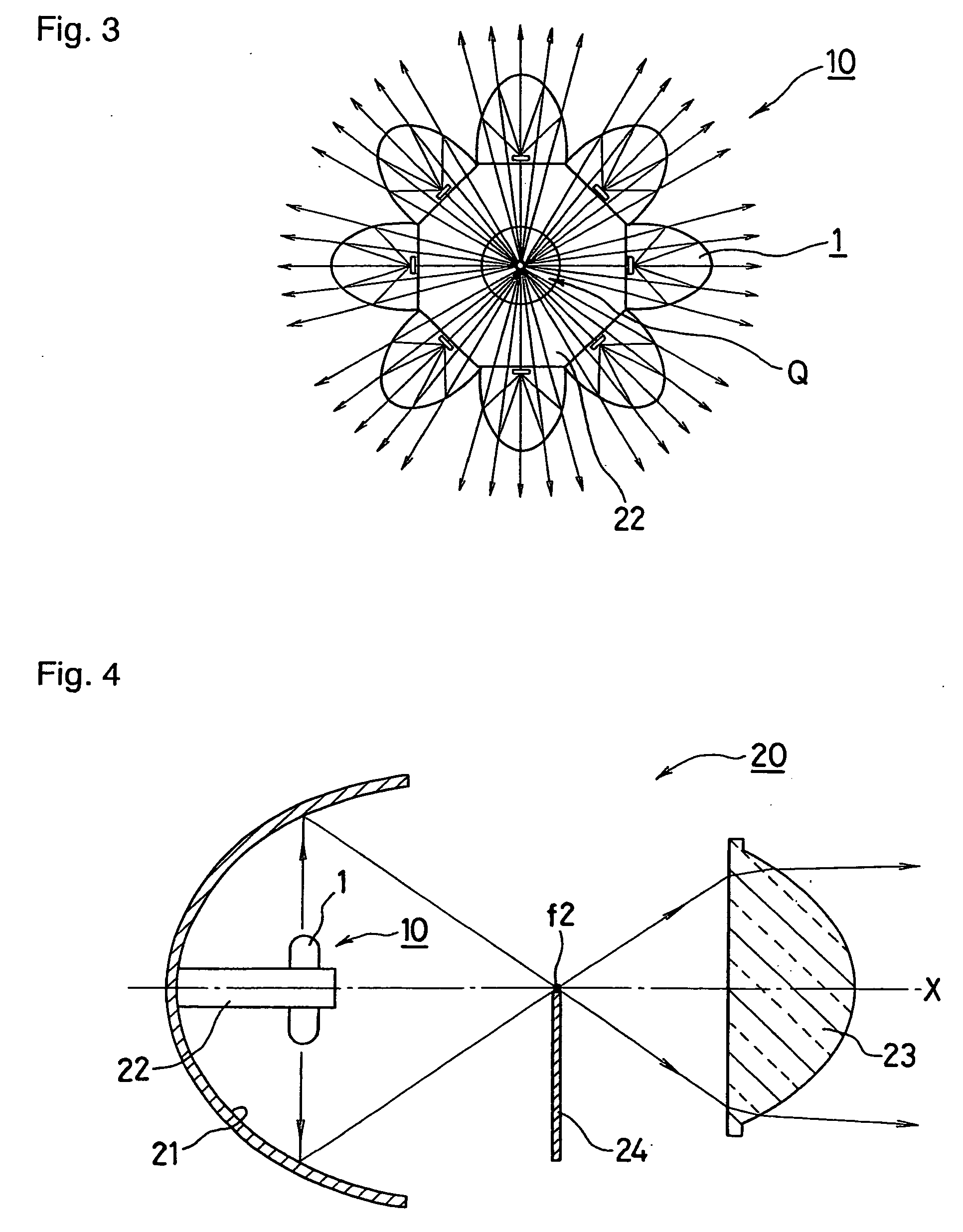
[0020] The present invention will be described next in detail with reference to embodiments shown in the figures. A modular LED is denoted with the reference numeral 1 in FIG. 1. A certain number of modular LEDs 1 can be combined to form a light source module 10 that serves as a single light source for a reflecting mirror 21 in a lamp 20 (see for example FIG. 4).

[0021] The modular LED 1 can include an LED chip 2, a base 3, and a lens 4. The LED chip 2 can be die-mounted on the base 3 that preferably includes a lead frame, for example, for attachment to the lamp 20 and for supply of power to the LED chip 2 as described later.

[0022] The lens 4 can be composed of a transparent material such as an epoxy resin, which covers the LED chip 2. The lens 4 can be configured to condense the light that is emitted at a wider emission angle from the LED chip 2, and lead the light to externally emit at an appropriate emission angle (for example, 30°).

[0023] The lens 4 can be appropriately shaped...


PUM


Abstract

A modular LED can include an LED chip, a base, and a lens. The lens preferably has a focus at a position spaced a certain distance behind the base to form a virtual light source image of the LED chip. Plural modular LEDs can be integrated into a lamp such that virtual light source images are superimposed. Thus, a light source module can serve as a single light source.

Description

[0001] This application claims the priority benefit under 35 U.S.C. §119 of Japanese Patent Application No. 2003-357827, filed on Oct. 17, 2003, which is hereby incorporated by reference. BACKGROUND OF THE INVENTION [0002] 1. Field of the Invention [0003] The present invention relates to a lamp and light source module. More particularly, the invention relates to a lamp that includes a reflecting mirror having a focus and that includes an LED as a light source. The lamp and light source module are particularly well adapted for use as a vehicle or vehicle related lamp. [0004] 2. Description of the Related Art [0005] In a conventional vehicle lamp that employs LED lamps as light sources, the LED lamps are arranged in such a manner as to direct optical axes thereof to the apex of a cone. In addition, a cylindrical optical guide is attached to each LED lamp to converge light from all the LED lamps to the apex of the cone. A reflective surface of a hyperboloid of revolution is arranged ne...

Claims


Application Information

Patent Timeline
Patent Type & Authority Applications(United States)
IPC IPC(8): F21S8/10F21S2/00F21S8/04F21Y101/02H01L33/48H01L33/54H01L33/56H01L33/60H01L33/62
CPCF21K9/00F21S48/115Y10S362/80F21V29/20F21Y2101/02F21V29/89F21K9/68F21Y2115/10F21S41/141F21S41/143F21S41/148F21S41/151
Inventor YATSUDA, YASUSHIEBISUTANI, TAKASHIKUSHIMOTO, TAKUYA
Owner STANLEY ELECTRIC CO LTD
Why Eureka
Try Eureka