High power architecture for power over Ethernet

a technology of ethernet and high power, applied in the field of power over local area networks, can solve the problems of no provision in the above standard, the above standard is limited to a powered device, etc., and achieve the effect of high power outpu

Active Publication Date: 2005-04-21
CISCO TECH INC
View PDF27 Cites 88 Cited by
  • Summary
  • Abstract
  • Description
  • Claims
  • Application Information

AI Technical Summary

Benefits of technology

[0016] In one embodiment the powered device is operable in accordance with the IEEE 802.3af standard. In another embodiment the powered device comprises at least one of: a wireless access point; a laptop computer; a desk top computer; a security camera having at least one of pan, tilt and zoom functionality; and an entrance control device. In yet another embodiment the combiner is located within the powered device. In yet another embodiment the combiner is located outside of the powered device.
[0017] In another exemplary embodiment the combiner is operable in a low power mode in the absence of the sensed combined high power signal. In yet another exemplary embodiment the control circuit is further operable to supply a low power signal to the load for operation in a low power mode in the absence of the combined high power signal. In a further exemplary embodiment the control circuit is further operable to signal the load of the low power mode.
[0018] In one embodiment the control circuit is a controller. In another embodiment the combiner further comprises at least one DC / DC converter. In yet another embodiment the combiner further comprises a first DC / DC converter associated with the first power input and a second DC / DC converter associated with the second power input. In one further embodiment the first DC / DC converter is connected in series with the second DC / DC converter. In another further embodiment the first DC / DC converter is connected in parallel with the second DC / DC converter. In a further embodiment the combiner further comprises a first PWM / resonance controller associated with the first DC / DC converter and a second PWM / resonance controller associated with the second DC / DC converter.
[0019] In another embodiment the combiner further comprises a transformer having a first primary associated with the first power input and a second primary associated with the second power input. In a further embodiment the transformer comprises a secondary associated with the combined high power.
[0020] The invention also provides for a method of supplying power to a powered device comprising the steps of: receiving a first power over a first set of wire pairs; receiving a second power over a second set of wire pairs; combining the first power and the second power; sensing the success of the combining of the first power and the second power; and enabling a combined high power output in response to the sensing.
[0021] In one embodiment the method further comprises the steps of: sensing an unsuccessful combining of the first power and the second power; comparing at least one of the first and the second received power to a reference; and supplying low power in response to the comparing. In a further embodiment the method further comprises the step of signaling the powered device of the supplied low power.

Problems solved by technology

The above standard is limited to a powered device (PD) having a maximum power requirement during operation of 12.95 watts.
Unfortunately, no provision has been made in the above standard for PDs requiring power in excess of the above maximum power requirement.
It is understood by those skilled in the art, that the above power limitation is primarily a function of the power carrying capabilities of the installed twisted wire pairs being utilized to deliver power.
Each of the above mentioned patents similarly observe the above power limitation, since this limitation is a function of the power carrying capabilities of the twisted wire pairs being utilized.

Method used


Image

  • High power architecture for power over Ethernet
  • High power architecture for power over Ethernet
  • High power architecture for power over Ethernet

Examples


first embodiment

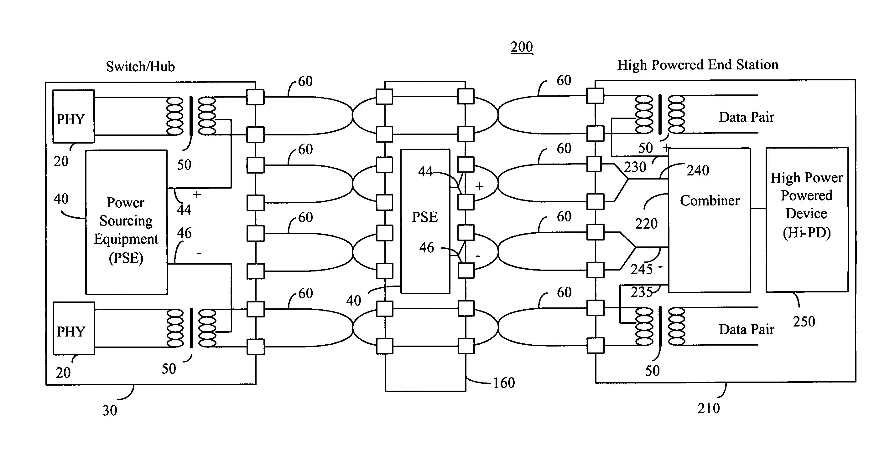
[0052]FIG. 2a illustrates a high level block diagram of a multiple path power feeding network configuration, herein designated network configuration 200, according to the principle of the invention. Network configuration 200 comprises: switch / hub equipment 30 comprising first and second PHY 20, first and second transformers 50 and endpoint PSE 40 having positive power output lead 44 and negative power output lead 46; first through eighth twisted pair connections 60; midspan power insertion equipment 160 comprising midspan PSE 40 having positive output lead 44 and negative power output lead 46; and high powered end station 210 comprising third and fourth transformers 50, power combiner 220 having first positive power input 230, first negative power input 235, second positive power input 240 and second negative power input 245 and high powered PD (Hi-PD) 250.

[0053] The primary of first and second transformers 50 are respectively connected to communication devices typically through fir...

second embodiment

[0058]FIG. 2b illustrates a high level block diagram of a multiple path power feeding network configuration, herein designated network configuration 300, according to the principle of the invention. Network configuration 300 comprises: high power switch / hub equipment 305 comprising first and second PHY 20, first and second transformers 50 and endpoint PSE 310 having a first power output comprising first positive power output lead 320 and first negative power output lead 325, a second power output comprising second positive power output lead 330 and second negative power output lead 335; first through fourth twisted pair connections 60; and high powered end station 210 comprising third and fourth transformers 50, power combiner 220 having first positive power input 230, first negative power input 235, second positive power input 240 and second negative power input 245 and high powered PD (Hi-PD) 250.

[0059] The primary of first and second transformers 50 are each connected to communic...

third embodiment

[0063]FIG. 2c illustrates a high level block diagram of a multiple path power feeding network configuration, herein designated network configuration 350, according to the principle of the invention. Network configuration 350 comprises: switch / hub equipment 35 comprising first and second PHY 20 and first and second transformers 50; first through eighth twisted pair connections 60; high power midspan power insertion equipment 360 comprising third and fourth transformers 50 and midspan PSE 310 having a first power output comprising first positive power output lead 320 and first negative power output lead 325, and further having a second power output comprising second positive power output lead 330 and second negative power output lead 335; and high powered end station 210 comprising fifth and sixth transformers 50, power combiner 220 having first positive power input 230, first negative power input 235, second positive power input 240 and second negative power input 245 and high powere...


PUM


Abstract

A combiner for use with a powered device having high power needs, the combiner comprising: a first power input adapted to receive a first power signal over a first set of wire pairs utilized to carry communication data; a second power input adapted to receive a second power signal over a second set of wire pairs, wherein the first power signal is combined with the second power signal to produce a combined high power signal; and a control circuit operable to sense the combined high power signal and to supply the combined high power signal to a powered device in response to the sensed combined high power signal. Also disclosed is a local area network adapted to supply power to powered devices over a plurality of paths utilizing the combiner, the local area network thus supplying high power to a powered device.

Description

RELATED APPLICATIONS [0001] This application claims priority from U.S. Provisional Patent Application Ser. No. 60 / 512,362 filed Oct. 16, 2003 entitled “POWERED DEVICE ASIC” the contents of which are incorporated herein by reference.BACKGROUND OF THE INVENTION [0002] The invention relates generally to the field of power over local area networks, particularly Ethernet based networks, and more particularly to an architecture enabling increased power for powered devices. [0003] The growth of local and wide area networks based on Ethernet technology has been an important driver for cabling offices and homes with structured cabling systems having multiple twisted wire pairs. The ubiquitous local area network, and the equipment which operates thereon, has led to a situation where there is often a need to attach a network operated device for which power is to be advantageously supplied by the network over the network wiring. Supplying power over the network wiring has many advantages includ...

Claims


Application Information

Patent Timeline
Patent Type & Authority Applications(United States)
IPC IPC(8): H04L12/10H04L12/413H04L12/56H04L29/06
CPCH04L12/10H04L69/24H04L49/40H04L49/351
Inventor PEKER, ARKADIYKORCHARZ, DRORFERENTZ, ALONDARSHAN, YAIR
Owner CISCO TECH INC
Why Eureka
Try Eureka