Medical instrument with indented loop and associated method

a medical instrument and indented loop technology, applied in the field of medical instruments, can solve the problems of obstructing the proper positioning of the snare within the patient, difficult to encircle the polyp with the cauterization loop, and different sizes of the polyp, and achieve the effect of simple and inexpensive manufacturing, effective use and simple structur

Active Publication Date: 2005-04-21
GRANIT MEDICAL INNOVATION
View PDF13 Cites 107 Cited by
  • Summary
  • Abstract
  • Description
  • Claims
  • Application Information

AI Technical Summary

Benefits of technology

[0008] A more specific object of the present invention is to provide such a snare or capture pouch that may be effectively used regardless of the specimen size.
[0009] Yet a further object of the present invention is to provide such a snare or capture pouch that is simple and inexpensive to manufacture.
[0014] The notches or dents facilitate the use of a distal end portion of the loop, which is bounded by the notches or dents on the proximal side and the bend or nose projection on the distal side, as an auxiliary loop necessarily having a size smaller than that of the entire loop. The notches or dents have a size and geometry adapted to releasably catch on the mouth rim of the tubular member, thereby preventing the loop from sliding uncontrollably either in an inward or outward direction. This catching facilitates an effective use of the distal end portion of the loop as a separate, auxiliary loop. At the onset of an endoscopic or other procedure using the auxiliary loop, a proximal portion of the main loop is disposed in a collapsed configuration inside the tubular member. Upon encirclement of a target tissue mass by the auxiliary loop, the auxiliary loop is drawn into the tubular member over the “energy hump” presented by the notches or dents.
[0019] Pursuant to yet another feature of the present invention, each of the loop sections includes a respective bend disposed between the nose projection and the respective notch or dent. These bends are concave towards the inside of the loop and provide the distal side of the open loop with a larger width than the proximal side of the open loop. More particularly, the loop is widest along a line extending from the bend in one of the loop sections to the bend in the other of the loop sections. The bends are located at the same distance from the nose projection so that the loop is provided with an enlarged distal end portion. The bends facilitate a sufficient opening of the entire loop for large polyp retrieval and of the partial loop or auxiliary loop for small polyp retrieval.

Problems solved by technology

A common problem in endoscopic procedures is that polyps come in different sizes.
If the snare used to harvest a polyp is too large, it is difficult to encircle the polyp with the cauterization loop.
Other tissue structures within the patient obstruct the proper positioning of the snare about the polyp.
In addition, upon placement of the snare about the polyp, the snare frequently does not optimally engage the polyp.
However, this approach is cumbersome in that if a larger snare, for example, has been introduced to capture and ressect a large polyp, that snare needs to be first withdrawn from the biopsy channel only to be replaced by a small (mini) snare to capture a smaller polyp.
This procedure is time consuming, and adds cost to the procedure because now two instruments instead of one need to be utilized.

Method used


Image

  • Medical instrument with indented loop and associated method
  • Medical instrument with indented loop and associated method
  • Medical instrument with indented loop and associated method

Examples


Embodiment Construction

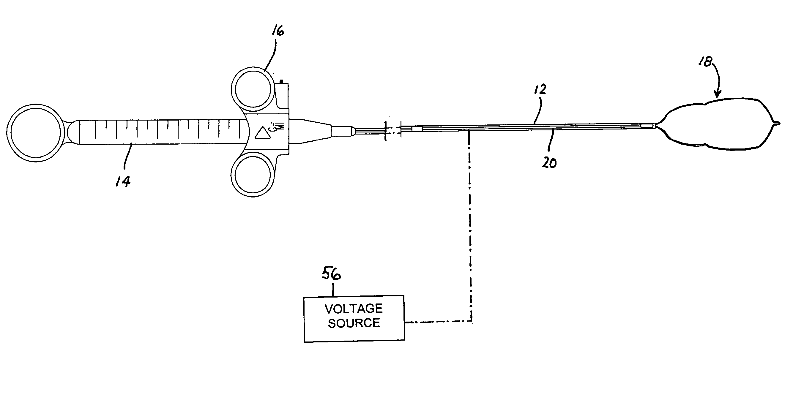
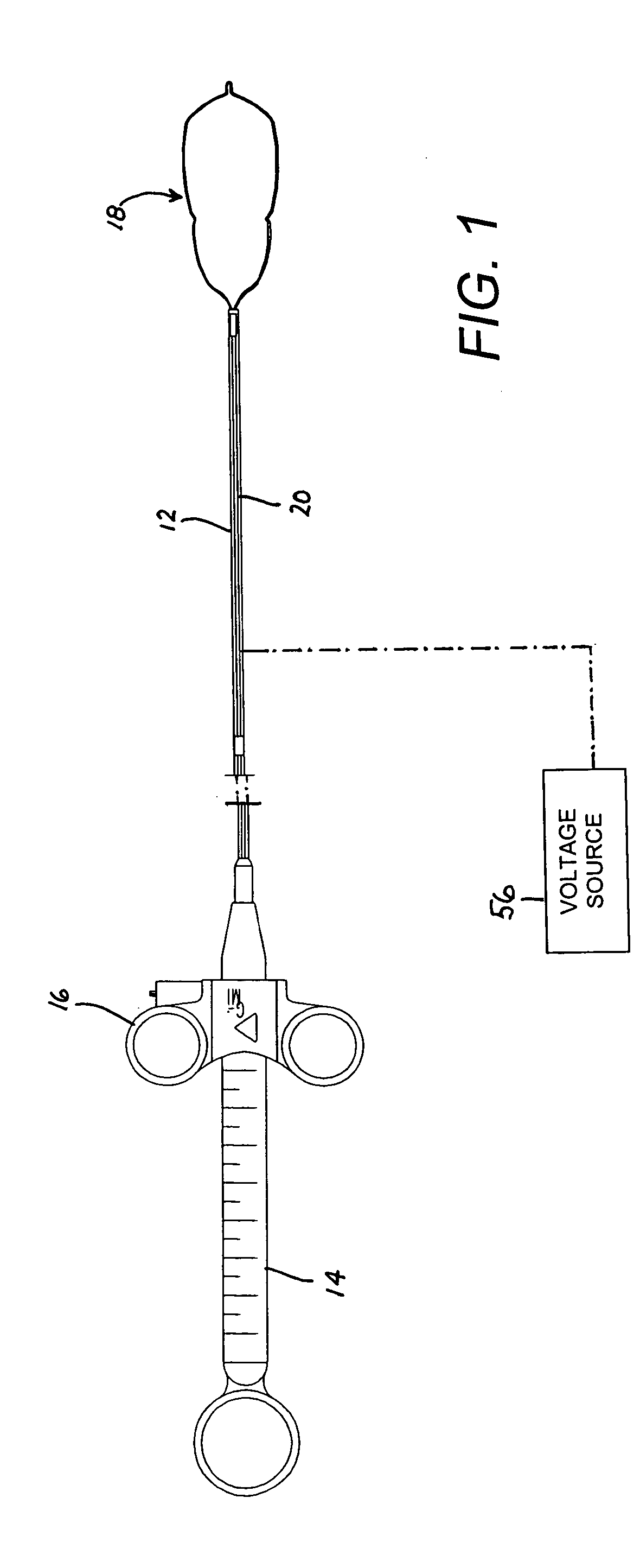
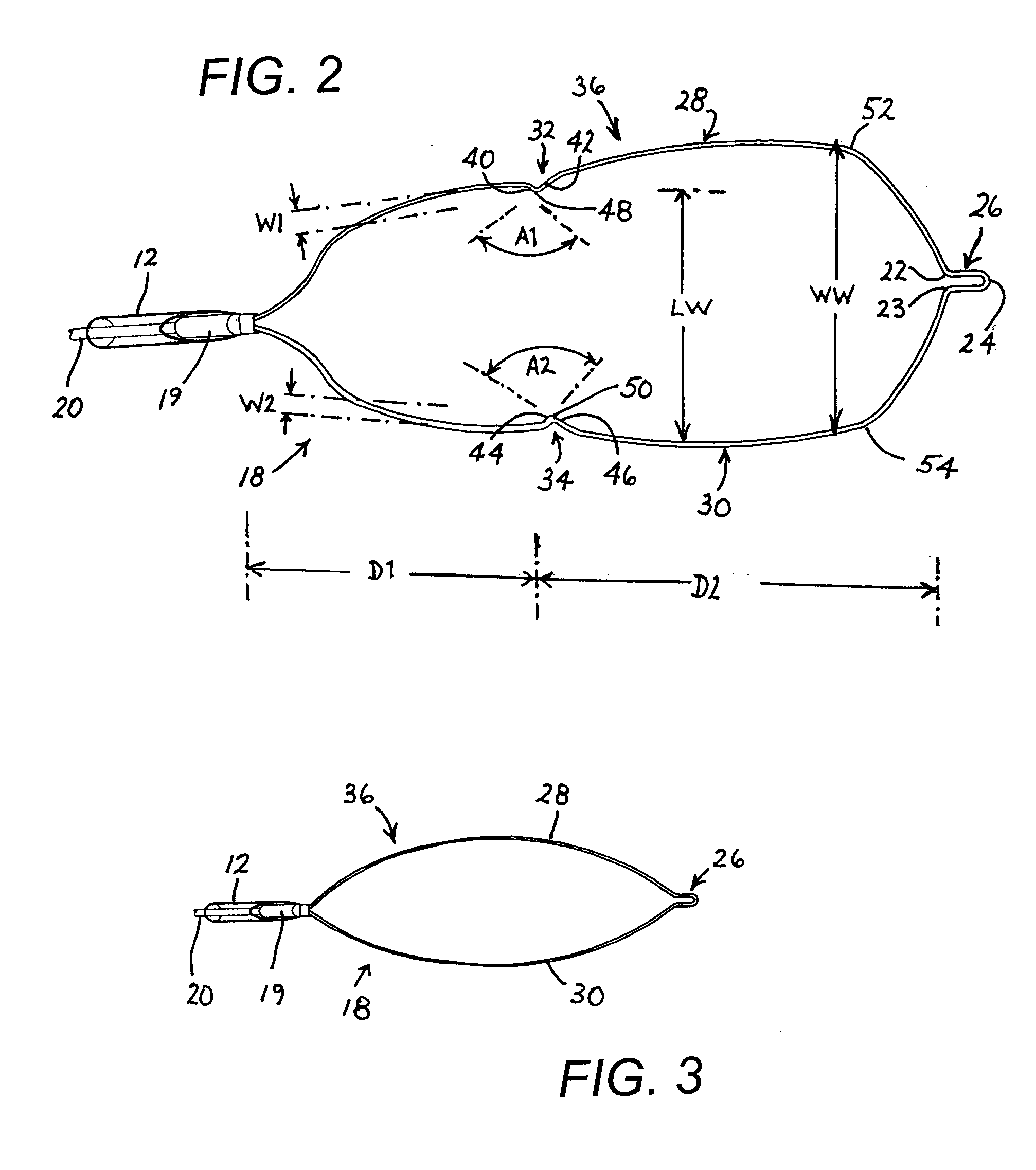
[0031] As depicted in FIG. 1, an endoscopic cauterization snare instrument comprises an elongate tubular member 12, a handle 14 with a slidable actuator 16, and a resilient loop 18 made of a wire or electrically resistant material as is well known in the art. Tubular member 12 is a catheter attached at its proximal end to handle 14. Loop 18 is attached to a distal end of an elongate rod or wire member 20 extending longitudinally through tubular member 12 to actuator 16. A metal tip element in the form of a sleeve 19 (FIG. 2) is inserted in the distal end of tubular member 12 and is rigidly fastened thereto. Sleeve 19 is a serves as a guide for loop 18 during ejection and retraction procedures. To that end, sleeve 19 is provided at a free end with a segment 21 that is rectangular in cross-section. In FIG. 1, actuator 16 is shown disposed in a most distal position relative to handle or grip 14. In that position of the actuator, loop 18 is in a fully extended and fully opened configura...


PUM


Abstract

A medical cauterization snare includes a tubular member such as a catheter, a rod or wire disposed at least partially inside the tubular member, and a resilient loop of a first size attached to a distal end of the rod or wire. The loop includes a nose on a side of the loop opposite the wire. The loop further includes two loop sections each extending between the wire and the nose. The loop sections are each formed with a respective notch or dent for enabling a use of the loop in a second size smaller than the first size. Positioning the loop relative to the tubular member so that the notches or dents are disposed at a mouth opening of the tubular member generates this secondary deployment configuration.

Description

BACKGROUND OF THE INVENTION [0001] This invention pertains to a medical instrument. More particularly, this invention pertains to a medical instrument utilizable in endoscopic procedures. This invention also relates to an associated method. [0002] Medical cauterization snares are essentially electrically energizable loops of wire. A cauterization snare is typically inserted in a collapsed configuration through the biopsy channel of an endoscope into a patient. Inside the patient, the cauterization snare is ejected from the endoscope biopsy channel and naturally expands to an opened configuration under the action of its own internal stresses. The snare is then manipulated from outside the patient and placed over a polyp or other tissue mass. The tubular member is then moved in the distal direction to close the loop about the base of the polyp or tissue mass. Then the cauterization loop is withdrawn in the proximal direction into the tubular member to sever the polyp. Electrical curre...

Claims


Application Information

Patent Timeline
Patent Type & Authority Applications(United States)
IPC IPC(8): A61B17/22A61B17/32A61B18/14
CPCA61B17/221A61B17/32056A61B2018/1407A61B2017/2212A61B17/3207A61B2017/00287
Inventor NAKAO, NAOMI L.
Owner GRANIT MEDICAL INNOVATION
Why Eureka
Try Eureka