Magnetorheological fluid damper

a damper and magnetorheological technology, applied in the direction of shock absorbers, mechanical devices, vibration suppression adjustments, etc., can solve the problems of insufficient damper geometries, flow patterns, and the range of stroking forces achievable with current mr materials,

Active Publication Date: 2005-04-28
GM GLOBAL TECH OPERATIONS LLC
View PDF36 Cites 21 Cited by
  • Summary
  • Abstract
  • Description
  • Claims
  • Application Information

AI Technical Summary

Problems solved by technology

However, the range of stroking forces achievable with current MR materials, flow patterns, and damper geometries are ...

Method used


Image

  • Magnetorheological fluid damper
  • Magnetorheological fluid damper
  • Magnetorheological fluid damper

Examples


Embodiment Construction

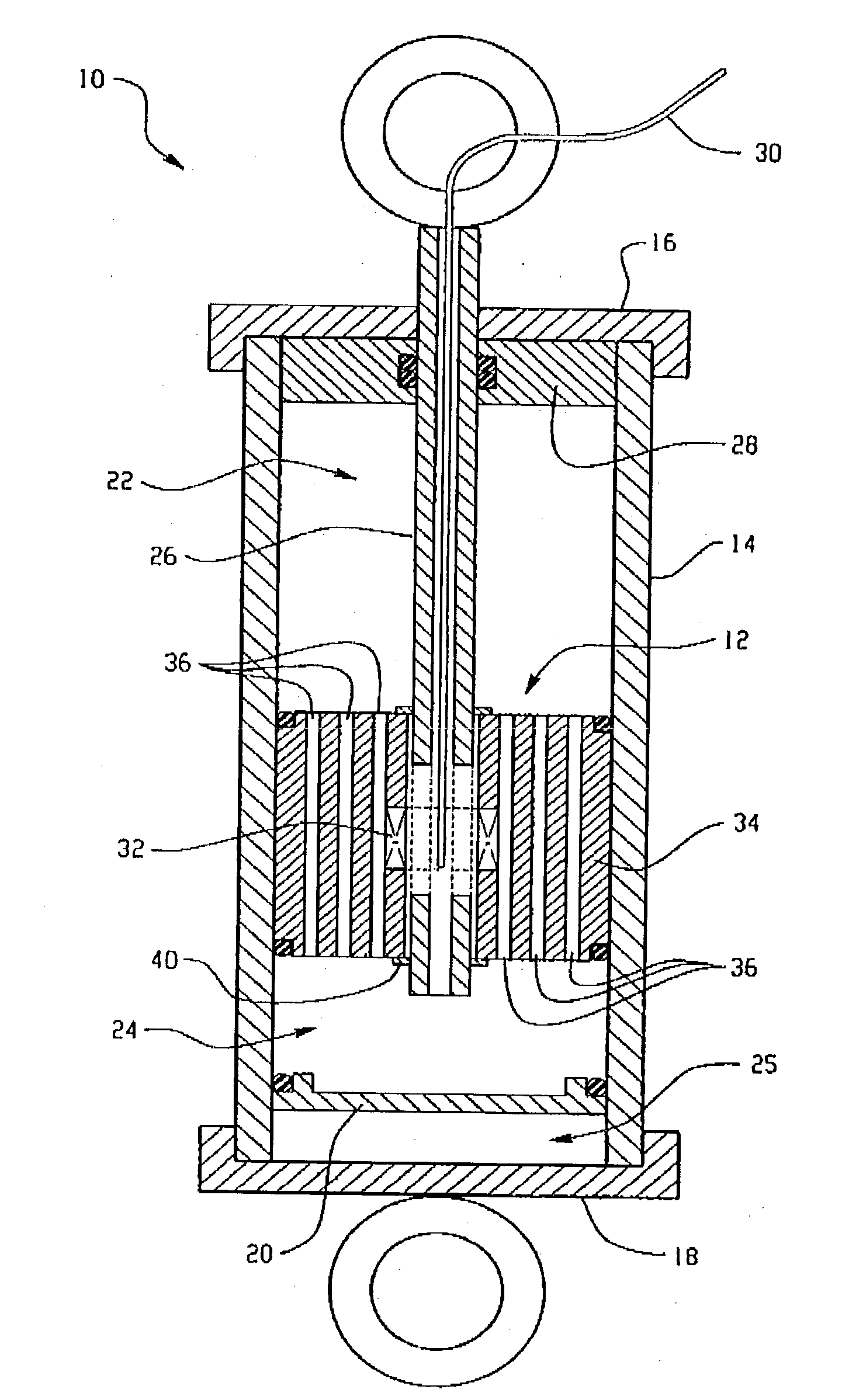
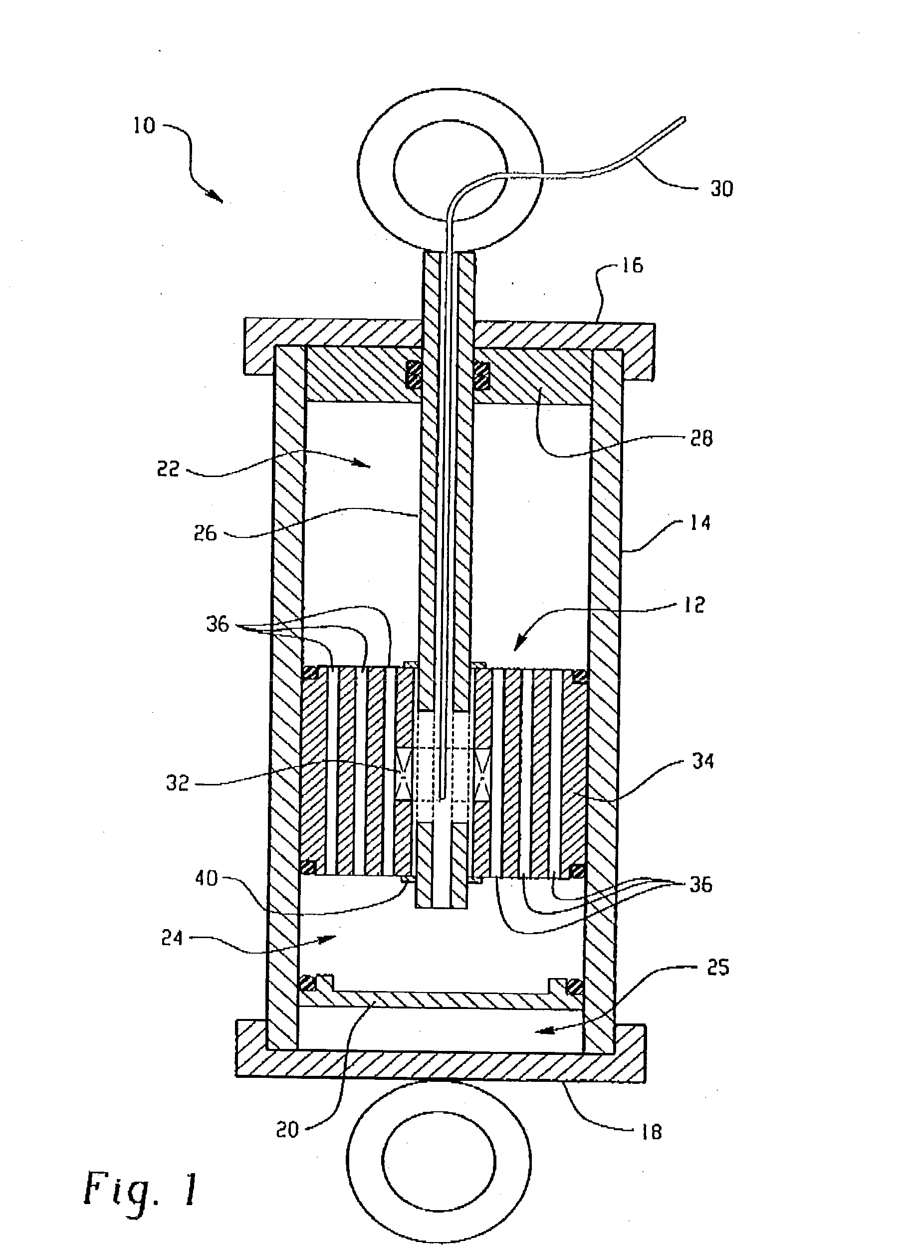
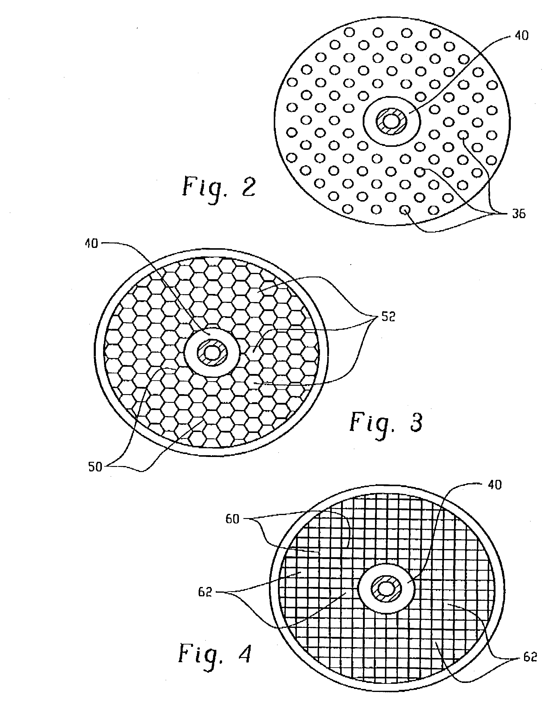
[0015] Disclosed herein is a magnetorheological fluid damper, also referred to herein as an MR damper. The MR damper is especially suitable for use in applications desiring damping control, and in a preferred embodiment, employs a design that provides an increase in the shear interface area per unit volume of the device, which enhances the stroking force, thereby overcoming some of the problems noted in the prior art. As will be discussed in greater detail, the MR damper as described herein preferably employs a piston of an open cell porous media to provide multiple fluid passageways. The fluid passageways may or may not be of uniform geometry and size.

[0016] It is known that a large turn-up ratio can be obtained with a reduction in off-state force and / or by improving / increasing the initial on-state force. The initial on-state force is generally dependent on the yield stress of the MR fluid, which is primarily dependent on the magnetic flux density in the fluid flow gaps. It has be...


PUM


Abstract

A magnetorheological damper device is provided having an increased shear interface area per unit volume of the device, which enhances the stroking force of the damper. The damper generally includes a cylindrically shaped housing; a magnetorheological fluid disposed in the cylindrically shaped housing; a piston assembly disposed within the cylindrically shaped housing in sliding engagement with the cylindrically shaped housing defining a first chamber and a second chamber, wherein the piston assembly comprises a plurality of cylindrically shaped fluid passageways extending from the first chamber to the second chamber, and an electromagnet; and a power supply in electrical communication with the electromagnet.

Description

BACKGROUND [0001] This disclosure generally relates to a magnetorheological fluid damper and more particularly, to a magnetorheological fluid damper providing an increased shear interface area per unit volume and / or mass of the damping device. [0002] Magnetorheological (MR) fluids belong to a class of controllable fluids. The essential characteristic of these fluids is their ability to reversibly change from a free-flowing, linear, viscous liquid to a semi-solid with a controllable yield strength in milliseconds when exposed to a magnetic field. In the absence of an applied field, MR fluids are reasonably well approximated as Newtonian liquids. [0003] A typical MR fluid has about 20 to about 40 percent by volume of relatively pure, soft iron particles, typically about 3 to about 5 microns, suspended in a carrier liquid such as mineral oil, synthetic oil, water, or glycol. A variety of proprietary additives similar to those found in commercial lubricants are commonly added to discour...

Claims


Application Information

Patent Timeline
IPC IPC(8): F16F9/53
CPCF16F9/535
Inventor BROWNE, ALAN LAMPEJOHNSON, NANCY L.NAMUDURI, CHANDRA SEKHAR
Owner GM GLOBAL TECH OPERATIONS LLC
Why Eureka
Try Eureka