Rotational transfer mechanism

Active Publication Date: 2005-04-28
PENTAX RICOH IMAGING CO LTD
View PDF9 Cites 11 Cited by
  • Summary
  • Abstract
  • Description
  • Claims
  • Application Information

AI Technical Summary

Benefits of technology

[0007] The present invention provides a rotational transfer mechanism which can reliably smoothly transfer a torque of a rotary input shaft to a rotary output shaft that are rotatable relative to each other even if dimensional errors occur in the cam surfaces, the torque transfer members and the rotary output shaft; moreover, the rotational transfer mechanism is unaffected by such dimensional errors even if miniaturized.
[0012] The rotational transfer mechanism can serve as a one-way clutch, wherein the circumferentially-uneven-width-space forming portion causes the torque transfer member to wedge between the cam surface and the torque transfer cylindrical surface to transfer a torque of the rotary input shaft to the hollow-cylindrical rotary output shaft when the rotary input shaft is rotated forward, and the circumferentially-uneven-width-space forming portion prevents the torque transfer member from wedging between the cam surface and the torque transfer cylindrical surface to prevent the torque of the rotary input shaft from being transferred to the hollow-cylindrical rotary output shaft when the rotary input shaft is rotated reversely.
[0020] The rotational transfer mechanism can serve as a one-way clutch, wherein the circumferentially-uneven-width-space forming portion causes the torque transfer member to wedge between the cam surface and the torque transfer cylindrical surface to transfer a torque of the hollow-cylindrical rotary input shaft to the rotary output shaft when the hollow-cylindrical rotary input shaft is rotated forward, and the circumferentially-uneven-width-space forming portion prevents the torque transfer member from wedging between the cam surface and the torque transfer cylindrical surface to prevent the torque of the hollow-cylindrical rotary input shaft from being transferred to the rotary output shaft when the hollow-cylindrical rotary input shaft is rotated reversely.
[0028] According to the present invention, a torque of the rotary input shaft can be reliably smoothly transferred to the rotary output shaft even if dimensional errors occur in the cam surfaces, the torque transfer members and the rotary output shaft; moreover, the rotational transfer mechanism is unaffected by such dimensional errors even if miniaturized, which makes it possible to transfer a torque of the rotary input shaft to the rotary output shaft smoothly with reliability.

Problems solved by technology

However, the occurrence of dimensional errors in the cam surfaces and the torque transfer members in the production thereof cannot be avoided.
Therefore, if such dimensional errors increase, each torque transfer member may come into contact with the associated cam surface at a point thereon which deviates from the predetermined point on the associated cam surface when the torque transfer members come into contact with the torque transfer cylindrical surface of the rotary output shaft; consequently, no torque can be transferred from the rotary input shaft to the rotary output shaft.
Furthermore, each torque transfer member may wedge between the associated cam surface and the torque transfer cylindrical surface by an excessive force to a degree that makes it impossible for each torque transfer member to come out between the associated cam surface and the torque transfer cylindrical surface.
These defects appear conspicuously especially when the one-way rotational transfer mechanism is miniaturized.

Method used


Image

  • Rotational transfer mechanism
  • Rotational transfer mechanism
  • Rotational transfer mechanism

Examples


first embodiment

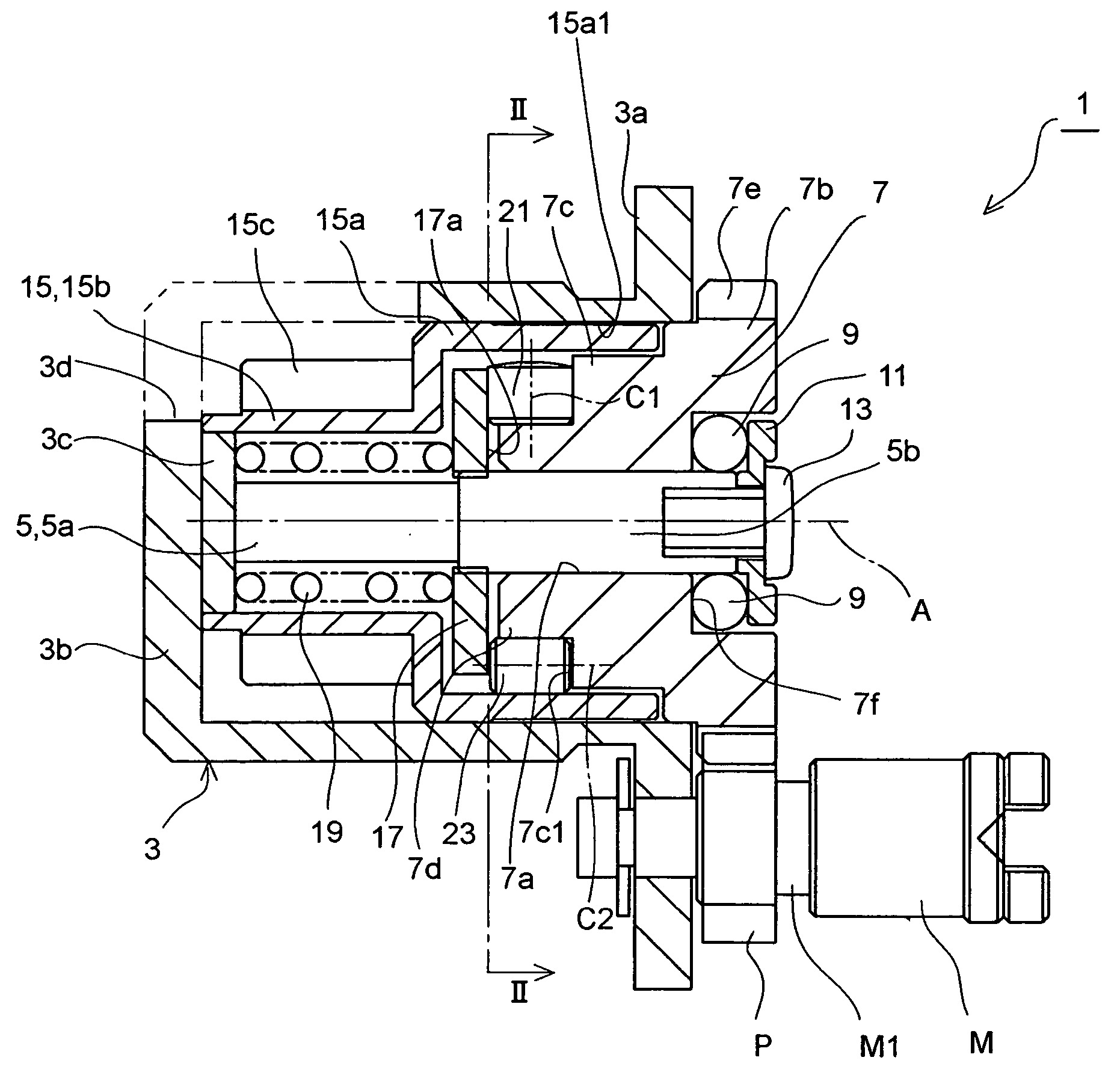
[0044]FIGS. 1 and 4 show the one-way rotational transfer mechanism (torque transfer mechanism) according to the present invention. This embodiment of the one-way rotational transfer mechanism 1 is incorporated in an autofocus camera in which a photographing mode can be selected between an autofocus mode (AF mode) and a manual focus mode (MF mode). Firstly, the structure of the one-way rotational transfer mechanism 1 will be discussed hereinafter.

[0045] In the following descriptions, the front and rear of the one-way rotational transfer mechanism 1 correspond to left and right sides in FIG. 1, respectively. The one-way rotational transfer mechanism 1 is provided with a cylindrical housing 3 whose front and rear ends are formed as a closed end and an open end, respectively. The cylindrical housing 3 is provided at a rear end thereof with an annular flange 3a which is fixed to a camera body (not shown) by set screws (not shown) to be positioned inside the camera body. The cylindrical h...

second embodiment

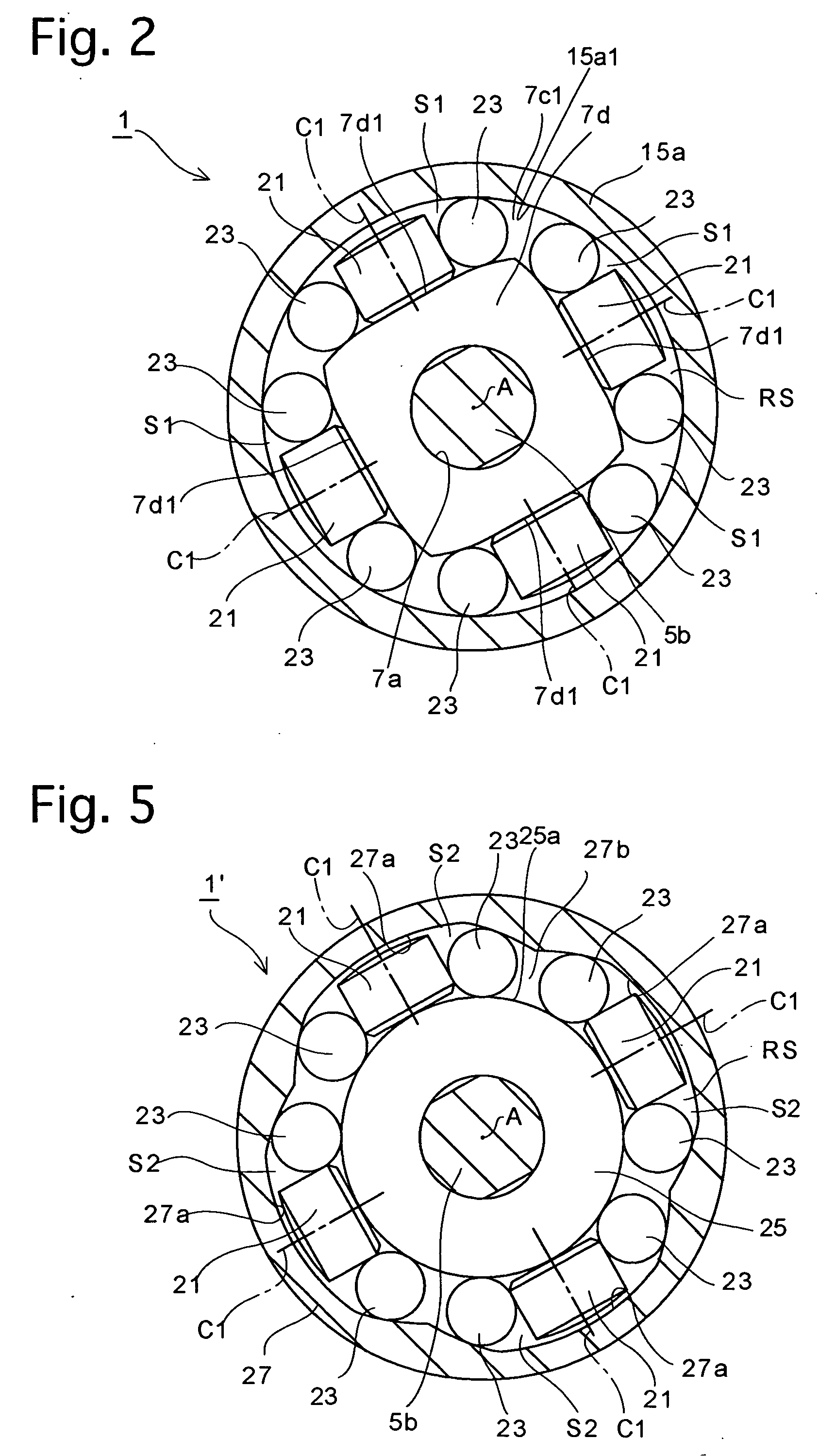
[0114]FIGS. 11 and 12 shows a modification of the one-way rotational transfer mechanism, in which a rotary input shaft and a rotary output shaft are positioned in a radially reversed fashion; namely, a rotary input shaft 42 is positioned radially outside a hollow-cylindrical rotary output shaft 40.

[0115] In the one-way rotational transfer mechanism (torque transfer mechanism) 30′ shown in FIGS. 11 and 12, the rotary output shaft 40 is rotatably fitted on the large-diameter portion 5b of the rotational shaft 5, while the hollow-cylindrical rotary input shaft 42 is positioned radially outside the rotary output shaft 40 to be rotatable about the axis of the rotational shaft 5. The rotary input shaft 42 is provided, on an inner peripheral surface thereof at equi-angular intervals in a circumferential direction of the rotary input shaft 42, with six circumferentially-uneven-depth grooves (circumferentially-uneven-width-space forming portions) 42a which have different radial depths at dif...


PUM


Abstract

A rotational transfer mechanism includes a rotary output shaft, a rotary input shaft positioned inside the rotary output shaft; a circumferentially-uneven-width-space forming portion having a cam surface, to form an accommodation space between the rotary input shaft and the torque transfer cylindrical surface; and a torque transfer member installed in the accommodation space. The cam surface shape is determined by defining a straight line through the rotational axis and the torque-transfer-member axis, defining an imaginary circle having the same shape as the torque transfer member on the straight line at a point where the imaginary-circle axis and the torque-transfer-member axis are symmetrical with respect to the rotational axis; determining a cam-surface determining circle which circumscribes the imaginary circle and the torque transfer member; and defining a circular arc which forms a part of the cam-surface determining circle as the cam surface.

Description

BACKGROUND OF THE INVENTION [0001] 1. Field of the Invention [0002] The present invention relates to a rotational transfer mechanism such as a one-way rotational transfer mechanism or a one-way clutch, and more specifically relates to the shape of a cam surface, provided in the rotational transfer mechanism, for transferring a torque of a rotary input shaft to a rotary output shaft. [0003] 2. Description of the Related Art [0004] Among conventional one-way rotational transfer mechanisms having a rotary input shaft and a hollow-cylindrical rotary output shaft positioned radially outside the rotary input shaft, wherein the rotary input shaft is driven by motor to transfer rotation of the rotary input shaft to the hollow-cylindrical rotary output shaft, a one-way rotational transfer mechanism which prevents the motor from being rotated by rotation of the rotary output shaft (i.e., prevents the rotary input shaft from being rotated by rotation of the rotary output shaft) when the rotary...

Claims


Application Information

Patent Timeline
IPC IPC(8): F16D41/06G02B7/08F16D41/064F16D41/08G02B7/04G02B7/09
CPCF16D41/064
Inventor IIKAWA, MAKOTOHAMASAKI, TAKUJI
Owner PENTAX RICOH IMAGING CO LTD
Why Eureka
Try Eureka