
Load floor assembly

a technology for loading floor and motor vehicles, which is applied in the direction of roofs, passenger spaces, transportation and packaging, etc., can solve the problems of not always producing adequate structural integrity, heavy weight and inconvenient assembly, and high cost,

Inactive Publication Date: 2005-04-28
BBI ENTERPRISES GROUP
View PDF24 Cites 29 Cited by
  • Summary
  • Abstract
  • Description
  • Claims
  • Application Information

AI Technical Summary

Benefits of technology

[0010] Accordingly, it would be advantageous to provide a load floor for a motor vehicle that is strong enough to support the loads consistent with a cargo area of the motor vehicle while also being lightweight.

Problems solved by technology

Presently, removable load floors are produced from blow molding a polypropylene material, possibly glass filled, which is extremely heavy and not structurally sound.
While glass-reinforced polyurethane is typically lighter than blow-molded polypropylene, it is extremely expensive and tends to flex under stress.
While these laminates have produced mass and cost savings, they have not always produced adequate structural integrity.

Method used


Image

  • Load floor assembly
  • Load floor assembly
  • Load floor assembly

Examples


Embodiment Construction

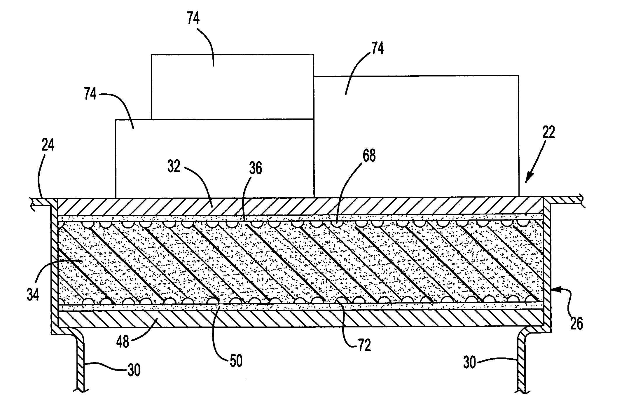
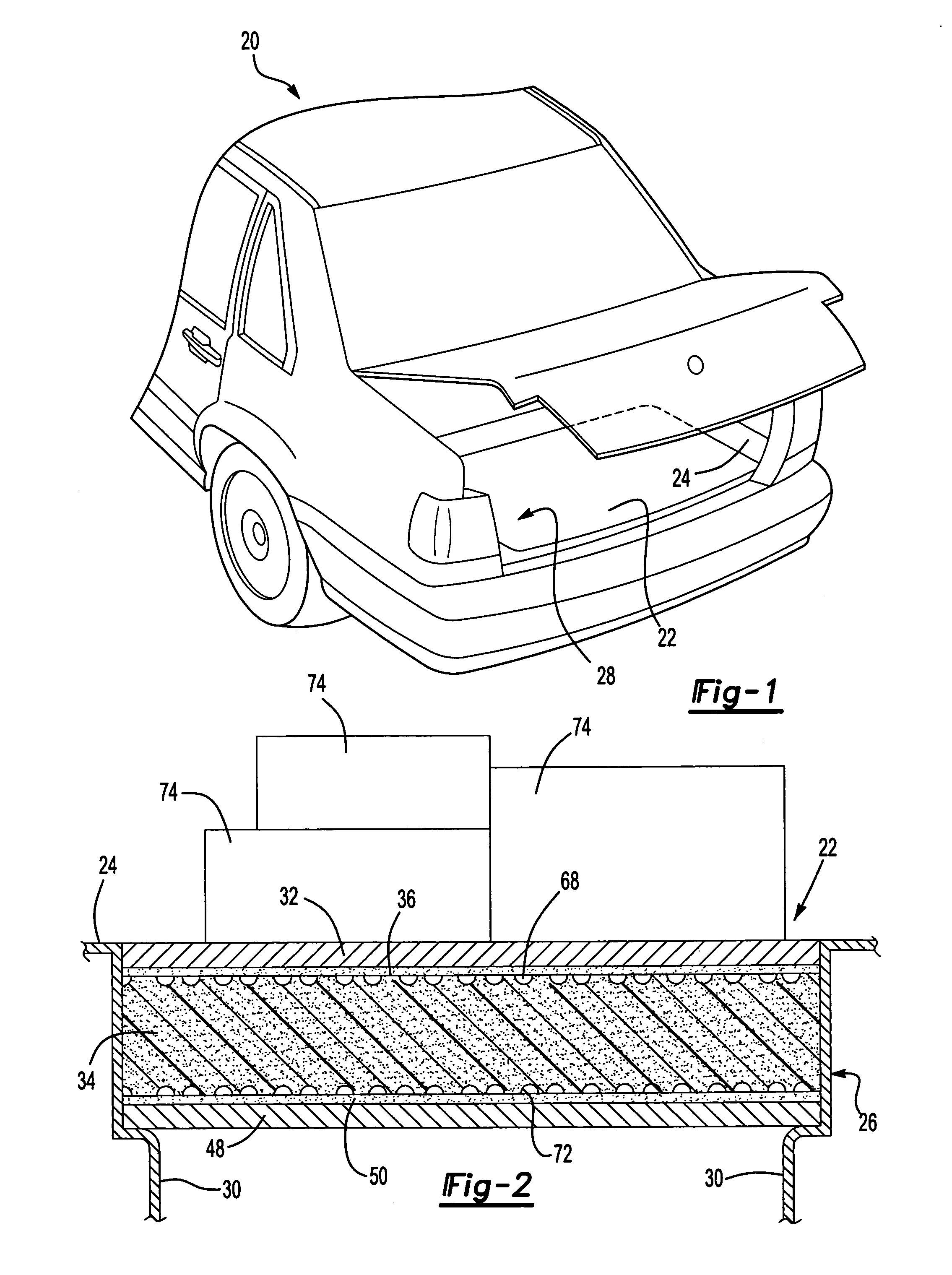
[0022] A motor vehicle is shown generally at 20. The motor vehicle 20 includes a floor panel 24, a tub portion 26, and a load floor 22. The tub portion 26, located below the floor panel 24, presents a cargo space 28 having an opening 30 in the floor panel 24. The load floor 22, which closes the opening 30, supports various loads 74 that are positioned upon the load floor 22.

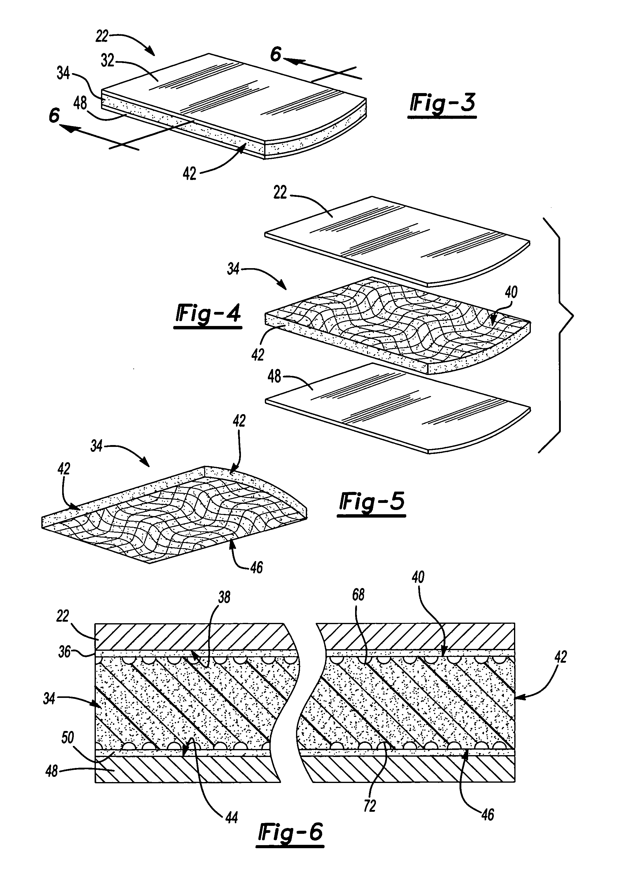
[0023] The load floor 22 includes a first facing layer 32, a substrate layer 34, and a first adhesive layer 36. The first facing layer 32 has a first inner surface 38. The first facing layer 32 includes hardboard or any other suitable piece of rigid material that is generally planar. The substrate layer 34 has a top surface 40 and a peripheral edge 42. The substrate layer 34 includes polymeric foam that is expanded polystyrene foam. However, any type of structural foam can be used. The first adhesive layer 36 is disposed between the surfaces 38, 40 for bonding the first facing layer 32 to the substrate layer 34....


PUM

PropertyMeasurementUnit
areaaaaaaaaaaa
stressaaaaaaaaaa
shapeaaaaaaaaaa

Abstract

A load floor (22) for a motor vehicle (20) has a foamed substrate layer (34) having a peripheral edge (42) and a facing layer (32), formed from hardboard or other sheet material. An adhesive layer (36) adheres the substrate layer (34) to the facing layer (32). Grooves (68, 70) are formed on a top surface (40) of the substrate layer (34) and extend to the peripheral edge (42) to provide an egress for fluids at the peripheral edge (42) during curing of the adhesive layer (36). The grooves (68, 70) are curved to prevent cracking of the substrate layer (34) under an applied load (74).

Description

RELATED APPLICATIONS [0001] The subject patent application claims priority to and all the benefits of U.S. Provisional Patent Application Ser. No. 60 / 499,482, filed on Sep. 2, 2003.BACKGROUND OF THE INVENTION [0002] 1. Field of the Invention [0003] The subject invention relates generally to an interior component for a motor vehicle which provides a structural surface. More specifically, the present invention relates to a load floor of a motor vehicle. [0004] 2. Description of the Prior Art [0005] The progression of motor vehicles, such as, for example, sport utility vehicles and station wagons, have included a desire to make full use of the space for storage. One such example is the inclusion of additional storage compartments located in a lower surface of a cargo area of the motor vehicle. These storage compartments are concealed by a structural component such as, for example, a load floor, which must also provide structural integrity to support the mass of heavy objects being tran...

Claims


Application Information

Patent Timeline
Patent Type & Authority Applications(United States)
IPC IPC(8): B60J7/00B60R13/01
CPCY10T428/2457B60R13/01
Inventor WOODSON, BRETT N.ENNIS, JAYYEE, BRANDON
Owner BBI ENTERPRISES GROUP
Learn More