Display devices

a technology of projection optics and micro-machined parts, applied in the direction of picture reproducers, identification means, instruments, etc., can solve the problems of cumbersome and expensive projection optics in relation to transmissive projection optics, loss generation of such devices, and cost and performance limitations of each devi

Inactive Publication Date: 2005-04-28
FLIXEL LTD
View PDF54 Cites 77 Cited by
  • Summary
  • Abstract
  • Description
  • Claims
  • Application Information

AI Technical Summary

Benefits of technology

[0016] Optionally, a levitation electrode is provided above the surface, outboard of the edge of the panel at the stable position parallel to the surface. The levitation electrode has the function, when flipping from the CLOSED to the OPEN position (hereinafter opening), of one or both of (1) raising the panel from a base on which it rests to negate stiction prior to the flipping and (2) inhibiting the flipping action. These functions are achieved by provi

Problems solved by technology

Each has limitations of cost and performance, especially with regards to light intensity on screen and to contrast between the bright and dark state.
The reflective nature of both these technologies impose projection optics which are cumbersome and expensive in relation to transmissive

Method used


Image

  • Display devices
  • Display devices
  • Display devices

Examples


Embodiment Construction

General Structure of the Panels

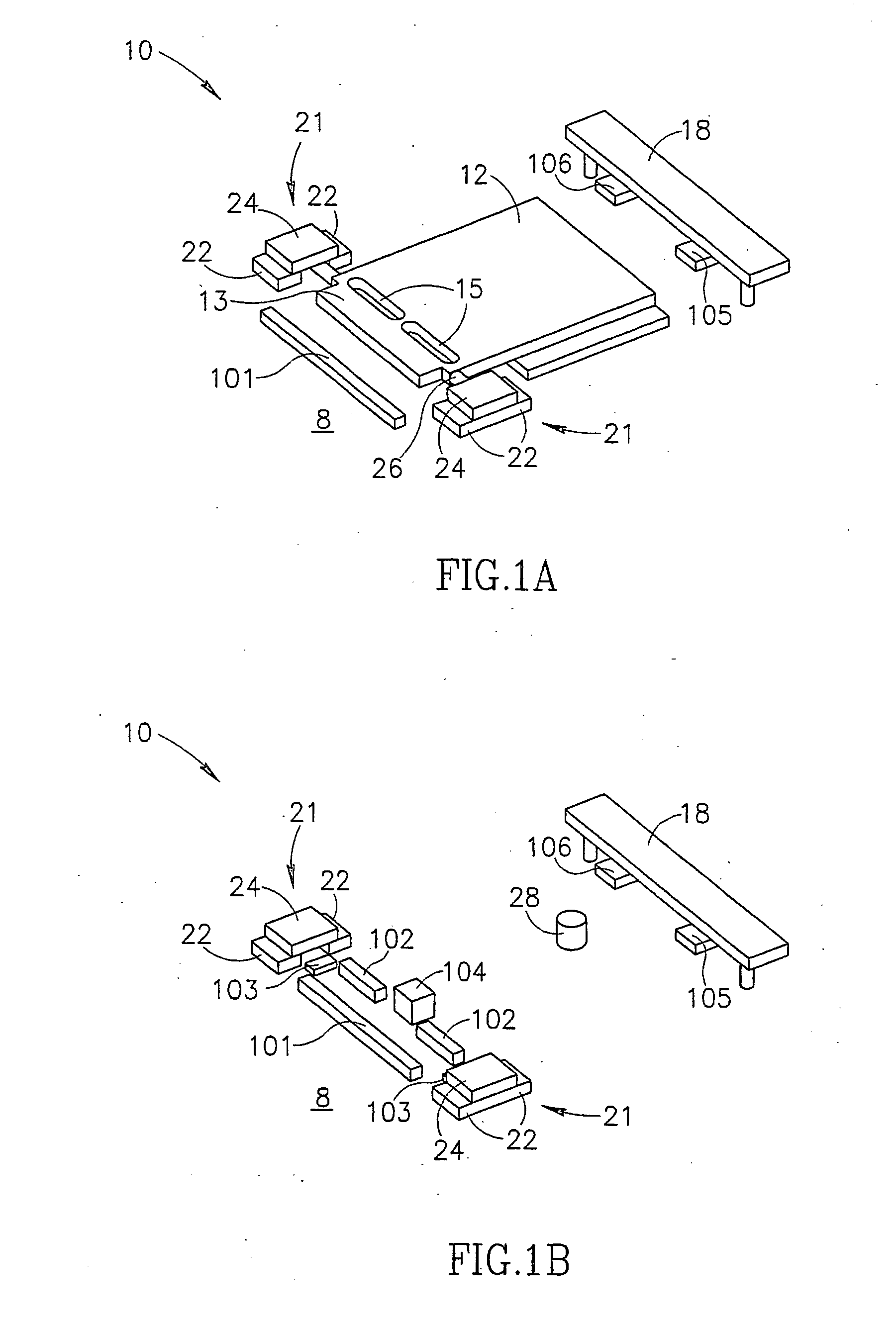
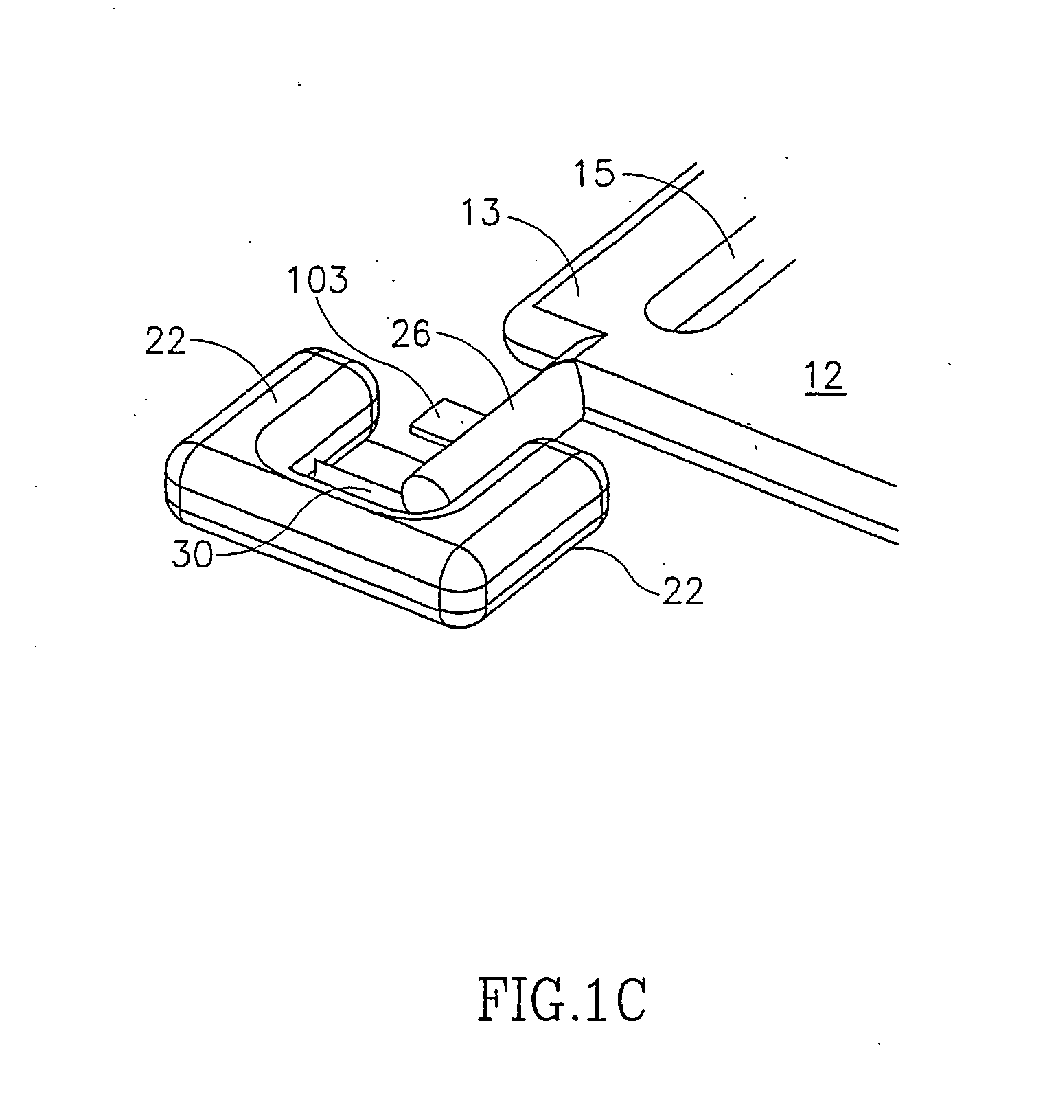
[0086]FIGS. 1A-1D show an overview of an exemplary pixel 10, in accordance with an embodiment of the invention. While this construction is presented as an example, many of the elements shown can have a different construction and some may be deleted altogether.

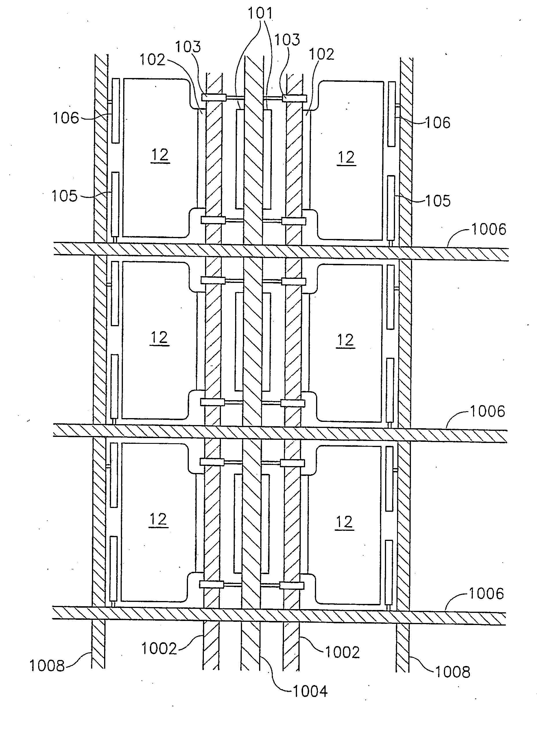
[0087] Pixel 10 comprises as its major components a flipping panel 12, closing electrode 101, opening electrode 102, clutch electrodes 103, stopping nub 104, row locking electrode 105, column locking electrode 106, levitation electrode 18 and a pair of sockets 21. The panels are formed with preferably rounded axles 26, which fit into sockets 21. The sockets comprise a lower, optionally wedge shaped, element 30 (sometimes referred to herein as a “knife 30”) formed with an upper edge on which the related axle rolls, a pair of side motion constraints 22 and an upper constraint 24. Each electrode is optionally formed with an optionally insulated nub 28 which minimizes the area of contact between th...


PUM


Abstract

Apparatus including: a substrate, having a substrate surface, at least a portion of which is transparent or apertured; and an array of objects each having a maximum dimension smaller than 1 mm attached to the substrate and having an axis about which the object can rotate, wherein the object has two stable positions, a first stable position at which the object covers a transparent or apertured portion of the substrate and a second stable position at which the transparent portion is at least partially uncovered.

Description

RELATED APPLICATIONS [0001] This application claims the benefit of U.S. Provisional Application 60 / 334,589 filed Dec. 3, 2001 and of U.S. Provisional application 60 / 361,321, filed Mar. 4, 2002. The present application is related generally to PCT application serial number PCT / IL99 / 00488, filed Sep. 8, 1999 and published as WO 00 / 52674, PCT / IL99 / 00130, filed Mar. 4, 1999 and published as WO 99 / 45423, PCT application PCT / IL00 / 00475, filed Aug. 6, 2000 and published as WO 02 / 13168, and PCT application PCT / 01 / 01076, filed Nov. 22, 2001 and published as WO 02 / 42826, the disclosures of all of which are incorporated herein by reference. [0002] Some of the subject matter of these applications is related to a best mode of carrying out the invention. This should not be construed as limiting the invention to embodiments which utilize all or even some of this matter.FIELD OF THE INVENTION [0003] The invention relates to the field of micro-machined and micro-formed devices with particular applica...

Claims


Application Information

Patent Timeline
IPC IPC(8): G09F9/37G02F1/17H04N9/31
CPCG09F9/372H04N9/3197H04N9/3102G02B26/08B81B3/00G09F9/37G02F1/03
Inventor HEINES, AMICHAIKARTY, ADIELCOHEN, ALLON
Owner FLIXEL LTD
Why Eureka
Try Eureka