
Method and apparatus for protection switch messaging on a shared mesh network

Inactive Publication Date: 2005-04-28
NORTEL NETWORKS LTD
View PDF7 Cites 33 Cited by
  • Summary
  • Abstract
  • Description
  • Claims
  • Application Information

AI Technical Summary

Benefits of technology

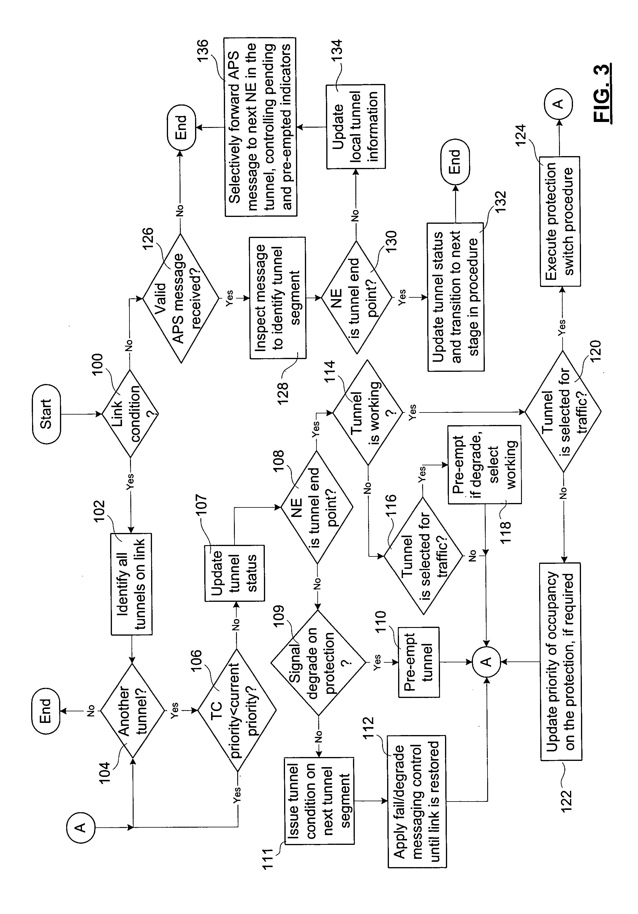
[0022] Receiving a tunnel status message from an adjacent NE may involve receiving a protection switch request used to erect a protection tunnel; or a cede message, or a preempt message used to release a protection tunnel. The message handling procedure, upon receipt of a protection switch request message, may involve identifying an occupant priority of data transport capacity supporting the tunnel segments of the tunnel, comparing the occupant priority with a priority contained in the protection switch request to determine whether the protection switch is locally allowable, forwarding the protection switch request over the tunnel segment if the protection switch is locally allowable, and forwarding a pended protection switch request over the tunnel segment if the protection switch is locally not allowable. The comparing the occupant priority with the protection switch request priority may involve deeming the protection switch request allowed if the data transport capacity is unoccupied, and the occupant priority is consequently null, deeming the protection switch request allowable if the occupant priority is less than the protection switch request priority, and deeming the protection switch request not allowable if the occupant priority is greater than or equal to the protection switch request priority. The receiving the protection switch request message may involve receiving the protection switch request from an adjacent NE in a first direction of the tunnel, and building the cross-connect if, the protection switch request is locally allowable, any occupant is removed, and an unpended switch request is received from the tunnel, in a direction opposite th

Problems solved by technology

It is well known in the art that the expense of providing and maintaining unused optical fiber and switching equipment is considerable.
In mesh-connected networks, i.e. NEs that are interconnected with arbitrary connectivity, it is generally not possible to use an equivalent to the node map.
Furthermore, unless restrictions are placed on protection channels / paths, so that only whole channels / paths (i.e. end-to-end) can be shared, a problem arises when one of the channel / path segments (provided by an optical fiber link between adjacent NEs) has a changed availability because of another channel / path passing through the segment.
Such restrictions would severely limit efficient utilization of protection data transport capacity.
The messaging required to enable the status of links within a tunnel to be used for priority-based preemption is problematic.
Messaging time delays become increasingly difficult to manage on mesh-connected networks that permit channels of arbitrary length, and provide multiple reservations of protection paths / channels.
These delays result in an increasing probability of collision, and are difficult to compensate for while maintaining low switch times. The channel / path end NE's notification of occupancy changes regarding each segment increases time delays for a number of reasons.
A first reason is that notifying ends of the protection tunnels on a segment causes a backlog of messaging at a single NE.
Each NE has a finite buffer space available for the APS channel, and when the buffer space is full, messages may be overwritten, leading to further problems.
Secondly, the number of APS messages that need to be sent is high, resulting in a high level of occupation of the buffers of the NEs in general.

Method used


Image

  • Method and apparatus for protection switch messaging on a shared mesh network
  • Method and apparatus for protection switch messaging on a shared mesh network
  • Method and apparatus for protection switch messaging on a shared mesh network

Examples


Embodiment Construction

[0035] The invention provides a messaging system and distributed processing scheme that permit protection switching on shared mesh networks.

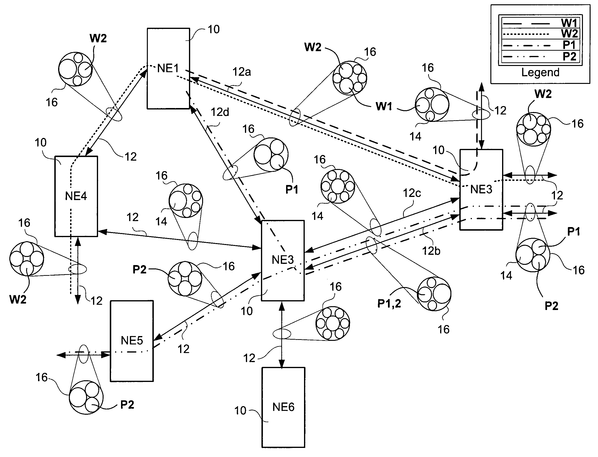
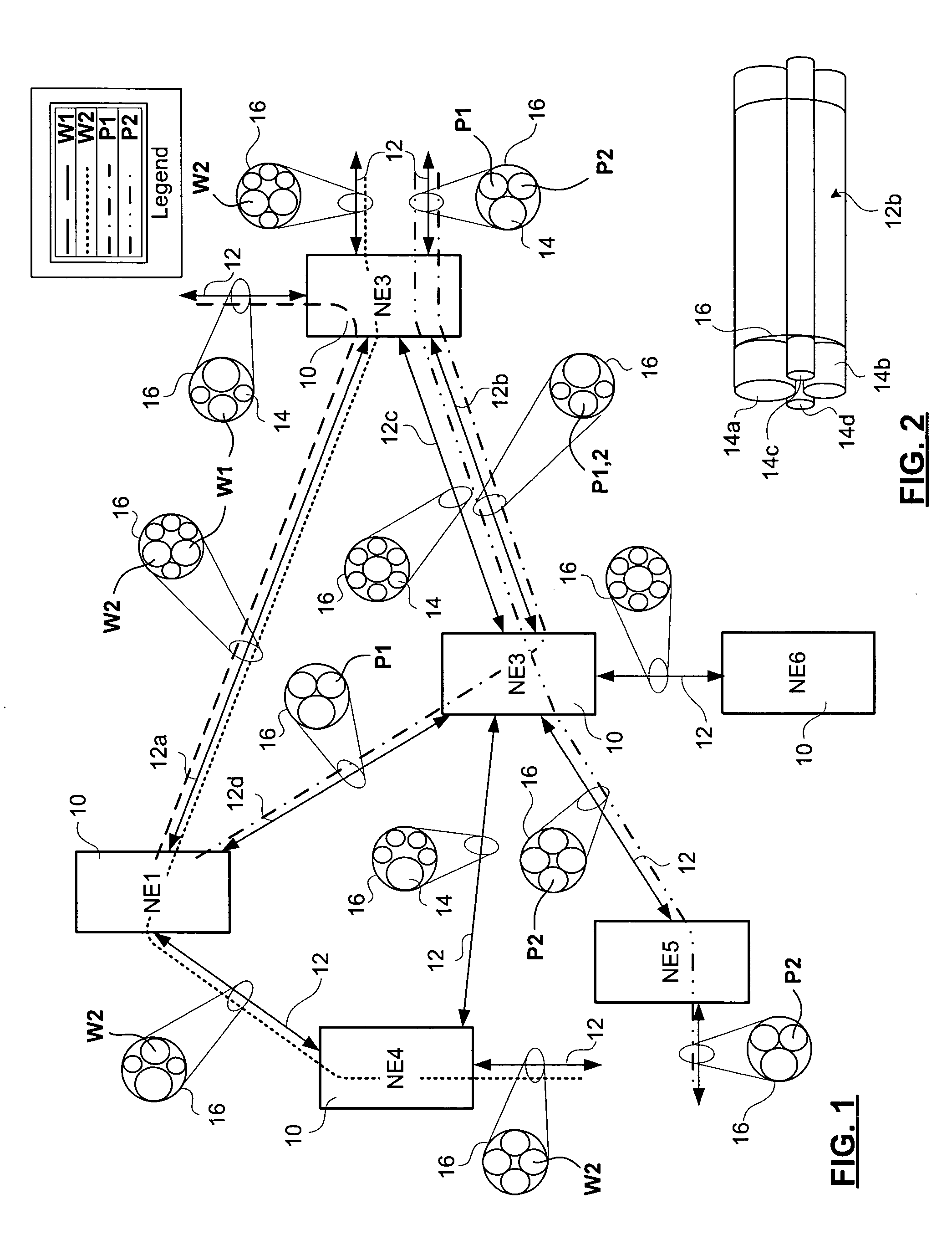
[0036]FIG. 1 schematically illustrates a portion of an optical network in which the invention may be deployed. The portion of the optical network includes six NEs 10 (NE1, NE2, NE3, NE4, NE5, NE6). The optical network is of a mesh topology. The NEs are interconnected in a generally unconstrained manner, and as such is neither a ring, nor a linear deployment. The mesh is of a bidirectional type wherein each optical fiber span that connects a first NE to a second is paired with an optical fiber span (providing equal data transport capacity) that interconnects the second NE to the first.

[0037] The NEs 10 exchange data over bidirectional (i.e. full duplex) links 12 (specific bidirectional links between the identified NEs 10 are identified as 12a,b,c,d). Each bidirectional link 12 provides a data transport capacity that involve one or more waveleng...


PUM


Abstract

A method for processing automatic protection switch (APS) messages at a network element in a tunnel provisioned across a data transport network in order to provide for distributed processing of protection switch request messages involves receiving new APS message at the NE; determining whether the NE is an end point of the tunnel, or a tandem of the tunnel and processing the message accordingly. If the NE is a tandem, message processing involves using local information about tunnel segments of the tunnel only maintained by the NE, to update the local information, and to selectively forward the updated information to adjacent NEs of the tunnel. If the NE is an end point, it updates a status of the tunnel. In a preferred embodiment all NEs are responsible for controlling pending and preemption indicators, and for initiating tunnel condition messages, and the end point NEs are responsible for initiating all other messages.

Description

CROSS-REFERENCE TO RELATED APPLICATIONS [0001] This is the first application filed for the present invention. MICROFICHE APPENDIX [0002] Not Applicable. TECHNICAL FIELD [0003] The present invention relates to protection switching in general, and to a method and apparatus for tunnel-based protection switching on data transport networks, in particular. BACKGROUND OF THE INVENTION [0004] Optical data transmission networks that have been deployed around the world, and a considerable fraction of today's data is transported over these networks. Part of the success of these networks, which include synchronous optical network (SONET) and other synchronous digital hierarchy (SDH) deployments, can be attributed to their high level of reliability. Reliability is provided by a number of protocol-based mechanisms, including failover protection. [0005] Failover protection is well known in the art. The principle of this reliability mechanism is to provide a backup path / channel for each working pat...

Claims


Application Information

Patent Timeline
IPC IPC(8): H04J3/14H04L1/00H04L12/24H04L12/26
CPCH04J3/14H04L43/0882H04L43/0817H04L41/0663
Inventor PHELPS, PETERCALDWELL, BRETTALLAYE-CHAN, MARKMCKENNA, GARYZHAO, SU
Owner NORTEL NETWORKS LTD
Learn More