Rotary anode type X-ray tube

a rotary anode and x-ray tube technology, applied in the direction of x-ray tube electrodes, electrical discharge tubes, electrical apparatus, etc., can solve the problems of large volume of the entire apparatus, inability to rotate smoothly and smoothly the cylindrical rotary structure, and increase the size and weight of each of the members. , to achieve the effect of high reliability, smooth rotation and stable operation

Active Publication Date: 2005-04-28
CANON ELECTRON TUBES & DEVICES CO LTD
View PDF9 Cites 9 Cited by
  • Summary
  • Abstract
  • Description
  • Claims
  • Application Information

AI Technical Summary

Benefits of technology

[0011] An object of the present invention is to provide a rotary anode type X-ray tube having a high reliability, which can be rotated smoothly and stably.

Problems solved by technology

However, if the rigidity of each of these members is increased, the size and the weight of each of these members are increased so as to give rise to the problem that the entire apparatus is rendered bulky.
In the both-side supported beam structure, however, a desired degree of parallelism between the stationary shaft and the cylindrical rotary structure is collapsed by the centrifugal force F acting on a heavy rotary anode, with the result that the cylindrical rotary structure tends to fail to be rotated smoothly.
As a result, depending on the position of the peak of the displacement curve, the degree of parallelism between the stationary shaft and the cylindrical rotary structure is rendered poor in the bearing region in which a radial bearing and a thrust bearing are to be formed.

Method used


Image

  • Rotary anode type X-ray tube
  • Rotary anode type X-ray tube
  • Rotary anode type X-ray tube

Examples


first embodiment

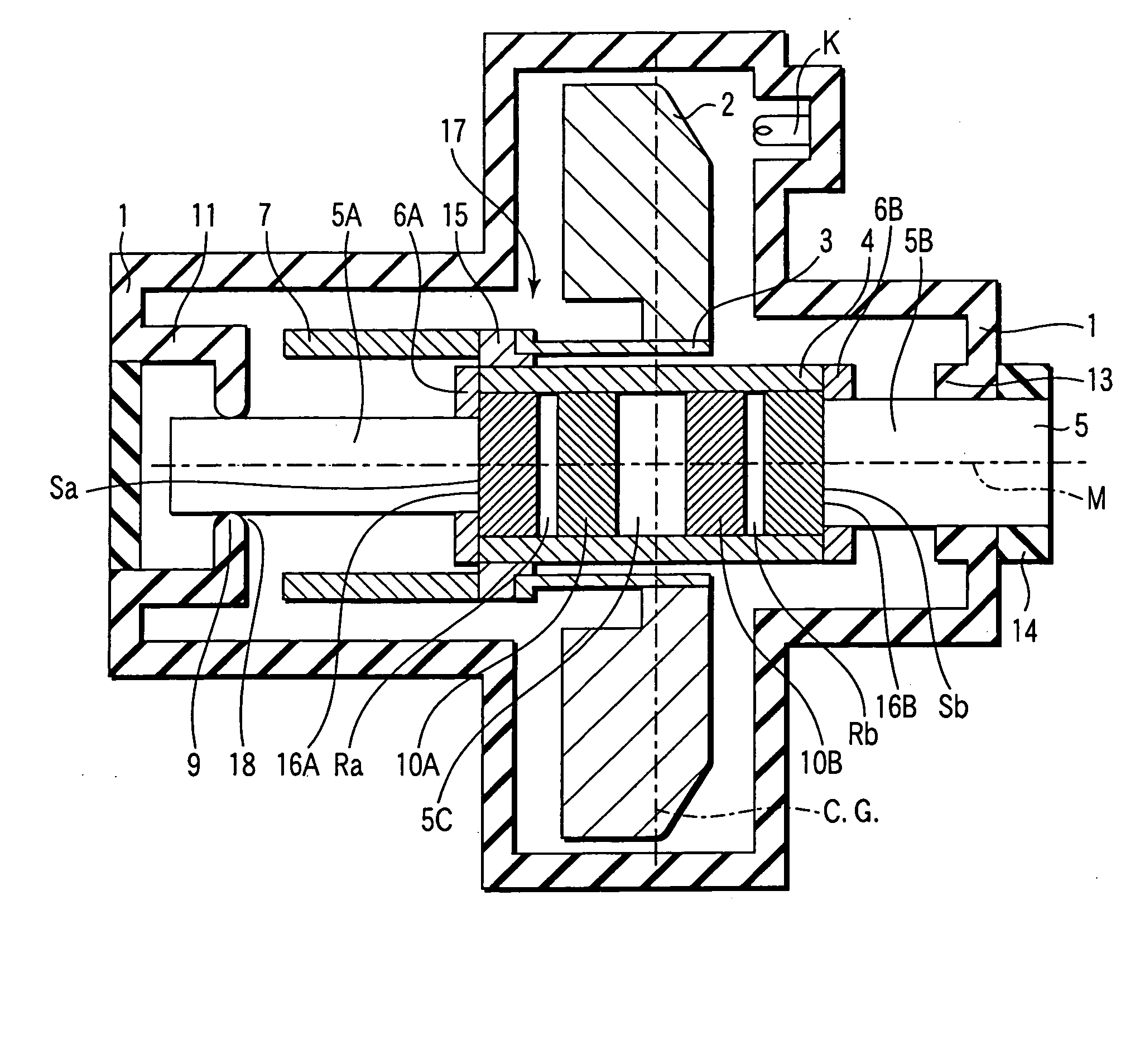
[0059]FIG. 1 is a cross sectional view schematically showing the construction of a rotary anode type X-ray tube according to the present invention.

[0060] As shown in FIG. 1, the rotary anode type X-ray tube of the present invention comprises a vacuum envelope 1 and a rotary anode 2 received in the vacuum envelope 1. The rotary anode 2 is rotated and used as a target. An electron beam emitted from a cathode K is impinged on the rotary anode 2 so as to cause an X-ray to be emitted from the rotary anode 2. The rotary anode 2 is fixed to a cylindrical coupling section 3 and is joined to a cylindrical portion 4 via the cylindrical coupling section 3 and a member 15 for allowing the cylindrical coupling section 3 to be mounted to the cylindrical portion 4.

[0061] A rotary structure 17 provided with the rotary anode 2 fixed thereto and including a rotor section 7, the coupling section 3, the mounting member 15 and the cylindrical portion 4 is supported in a rotatable condition by radial be...

second embodiment

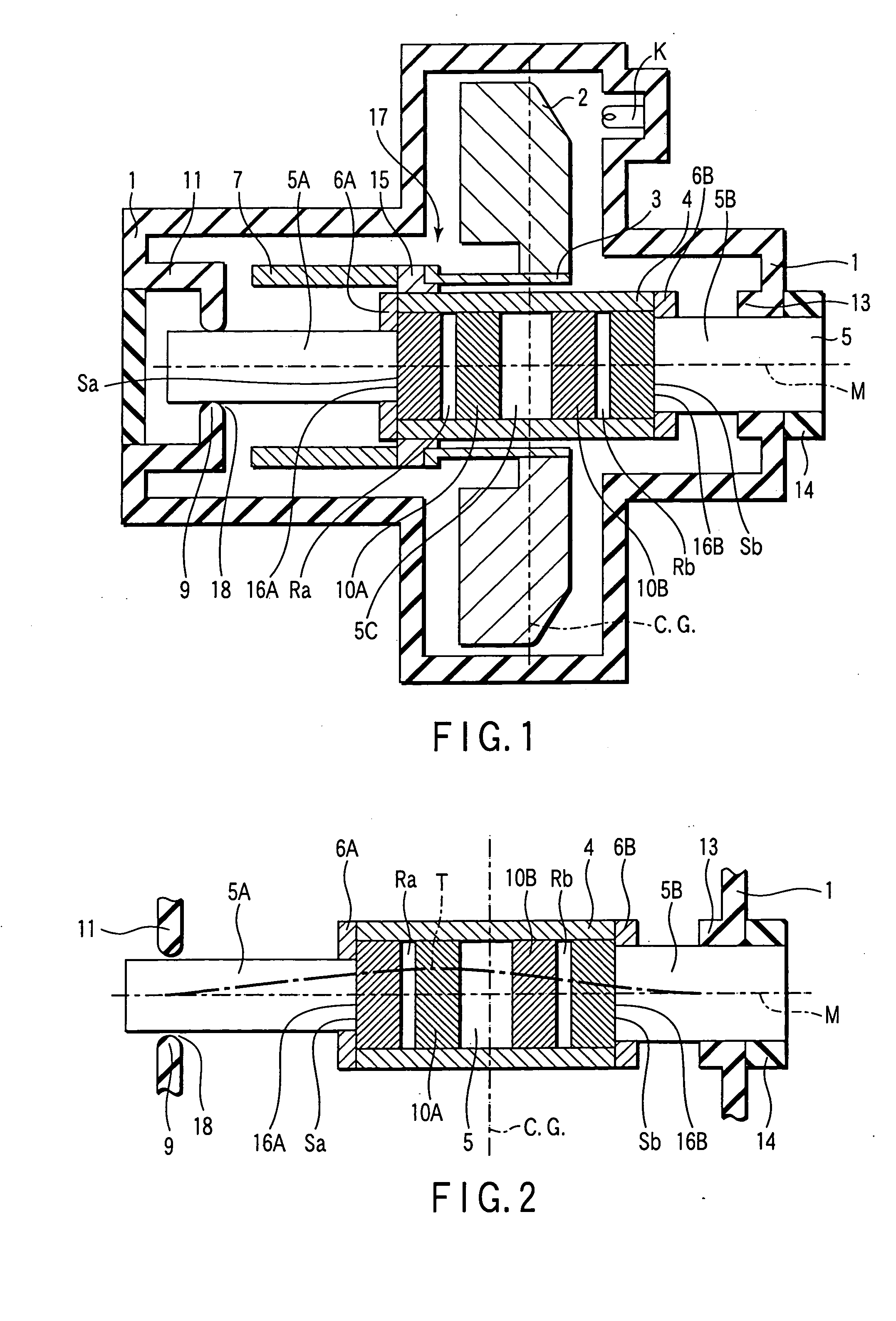
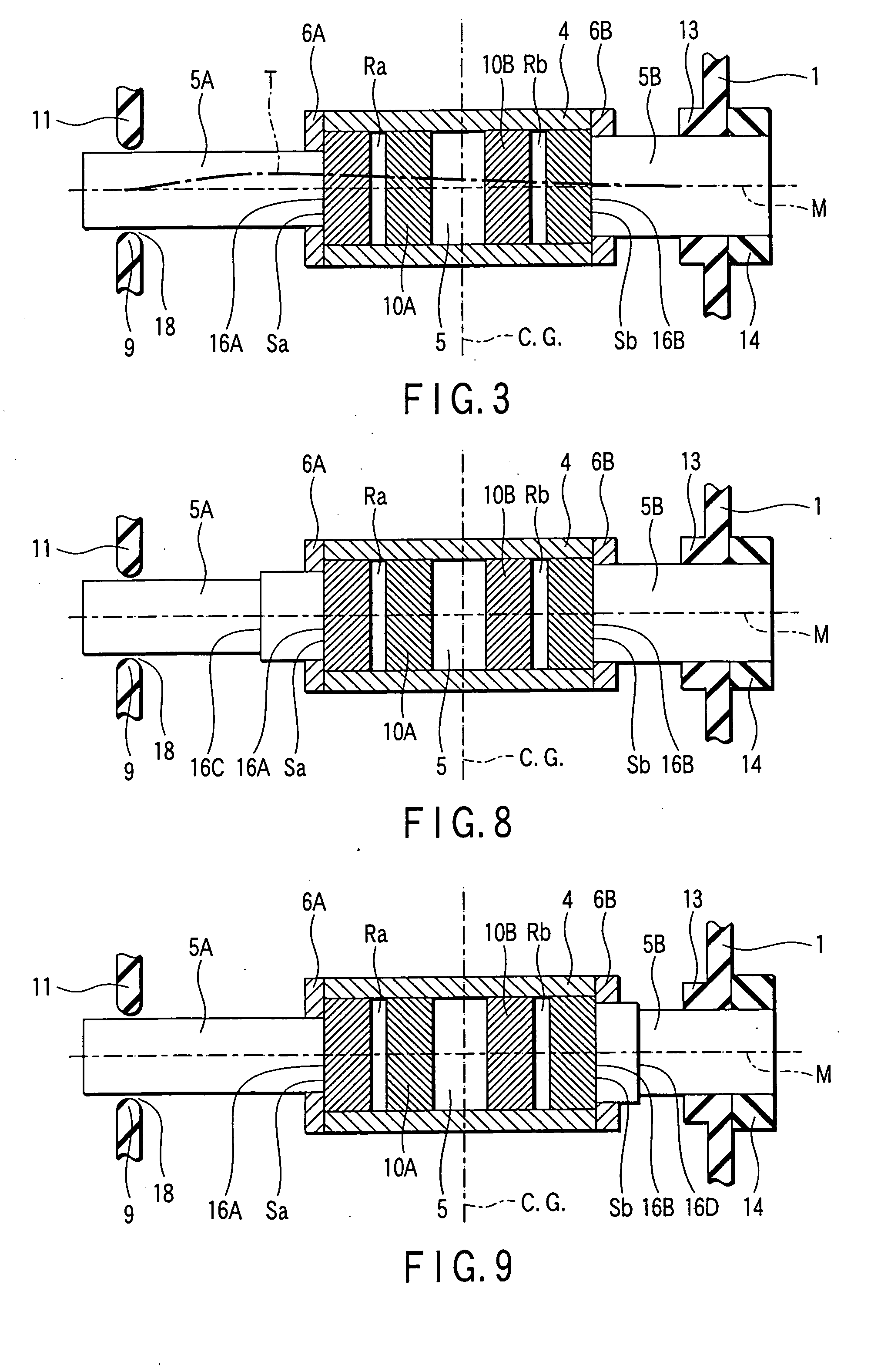
[0089] A rotary anode type X-ray tube according to the present invention will now be described with reference to FIG. 8.

[0090]FIG. 8 shows the rotary mechanism consisting of the radial bearings Ra, Rb, the thrust bearings Sa, Sb, the cylindrical portion 4, the stationary shaft 5, and the sections 5A, 5B of the stationary shaft 5, which are included in the rotary anode type X-ray tube shown in FIG. 1, and the supporting structure thereof. Those portions shown in FIG. 8 which correspond to the portions shown in FIG. 1 are denoted by the same reference numerals so as to avoid the overlapping description.

[0091] In the rotary anode type X-ray tube shown in FIG. 8, the first section 5A is formed of several portions differing from each other in the value of the bending rigidity. In the example shown in FIG. 8, the first section 5A is formed such that first and second shafts differing from each other in the diameter are joined to each other in a manner to form a stepped portion. However, t...

third embodiment

[0095] A rotary anode type X-ray tube according to the present invention will now be described with reference to FIG. 9. Specifically, FIG. 9 shows the rotary mechanism included in the rotary anode type X-ray tube and the supporting structure thereof like FIG. 8. Those portions shown in FIG. 9 which correspond to the portions shown in FIG. 1 are denoted by the same reference numerals so as to avoid the overlapping description.

[0096] In the structure shown in FIG. 9, the first section 5A which is supported with tilting capability has a uniform bending rigidity over the entire region. On the other hand, the second section 5B that is supported stationary is formed of several portions differing from each other in the value of the bending rigidity. In the example shown in FIG. 9, the second section 5B includes first and second shaft portions that are joined to each other in a manner to form a stepped portion. However, the construction of the second section 5B is not limited to that shown...


PUM


Abstract

In a rotary anode type X-ray tube, a rotary anode and a rotary structure supporting the anode are arranged within the vacuum envelope. A stationary shaft has a middle section which is fitted into a cylindrical portion of the rotary structure, and a dynamic pressure type radial bearing is arranged between the cylindrical portion and the middle section. The stationary shaft also has a first section between one end of the middle section and one end of the stationary shaft, and a second section between the other end of the middle section and the other end of the stationary shaft, which are fixed to the vacuum envelope. A transverse stiffness of the second section is set to be larger than a transverse stiffness of the first section, and a center of gravity is positioned in the middle section.

Description

CROSS-REFERENCE TO RELATED APPLICATIONS [0001] This application is based upon and claims the benefit of priority from prior Japanese Patent Application No. 2003-307392, filed Aug. 29, 2003, the entire contents of which are incorporated herein by reference. BACKGROUND OF THE INVENTION [0002] 1. Field of the Invention [0003] The present invention relates to a rotary anode type X-ray tube, particularly, to a rotary anode type X-ray tube in which the rotary shaft is supported by a dynamic slide bearing. [0004] 2. Description of the Related Art [0005] The conventional rotary anode type X-ray tube is disclosed in Japanese Patent No. 3,139,873 and U.S. Pat. No. 5,838,763 and, thus, is already known to the public. In the rotary anode type X-ray tube disclosed in Japanese Patent No. 3,139,873, an electron beam generated from the cathode is impinged on a rotary anode that is rotated as a target so as to cause X-rays to be emitted from the rotary anode. The rotary anode is fixed to a cylindric...

Claims


Application Information

Patent Timeline
Patent Type & Authority Applications(United States)
IPC IPC(8): H01J35/10
CPCH01J35/101H01J2235/106H01J2235/1006H01J35/104
Inventor FUKUSHIMA, HARUNOBUYOSHII, YASUOHATTORI, HITOSHIKITADE, KOICHIIWASE, MITSUONAKAMUTA, HIRONORI
Owner CANON ELECTRON TUBES & DEVICES CO LTD
Why Eureka
Try Eureka