Nanoporous diaphragm for electromagentic transducer

a diaphragm and electromagentic technology, applied in the field of electromagentic transducers, can solve the problems of less efficient transducer and significant increase in diaphragm mass

Inactive Publication Date: 2005-04-28
TURNMIRE PATRICK M +2
View PDF3 Cites 20 Cited by
  • Summary
  • Abstract
  • Description
  • Claims
  • Application Information

AI Technical Summary

Problems solved by technology

These solutions, such as the laminated dome structure, do offer some measure of increased rigidity of the diaphragm, but at the expense of significantly increased mass of the diaphragm.
The more massive the diaphragm (and other moving parts), the less efficient the transducer will be, and the more power (magnetic and / or electrical) it will require to effect an adequate acceleration of the diaphragm.

Method used


Image

  • Nanoporous diaphragm for electromagentic transducer
  • Nanoporous diaphragm for electromagentic transducer
  • Nanoporous diaphragm for electromagentic transducer

Examples


Embodiment Construction

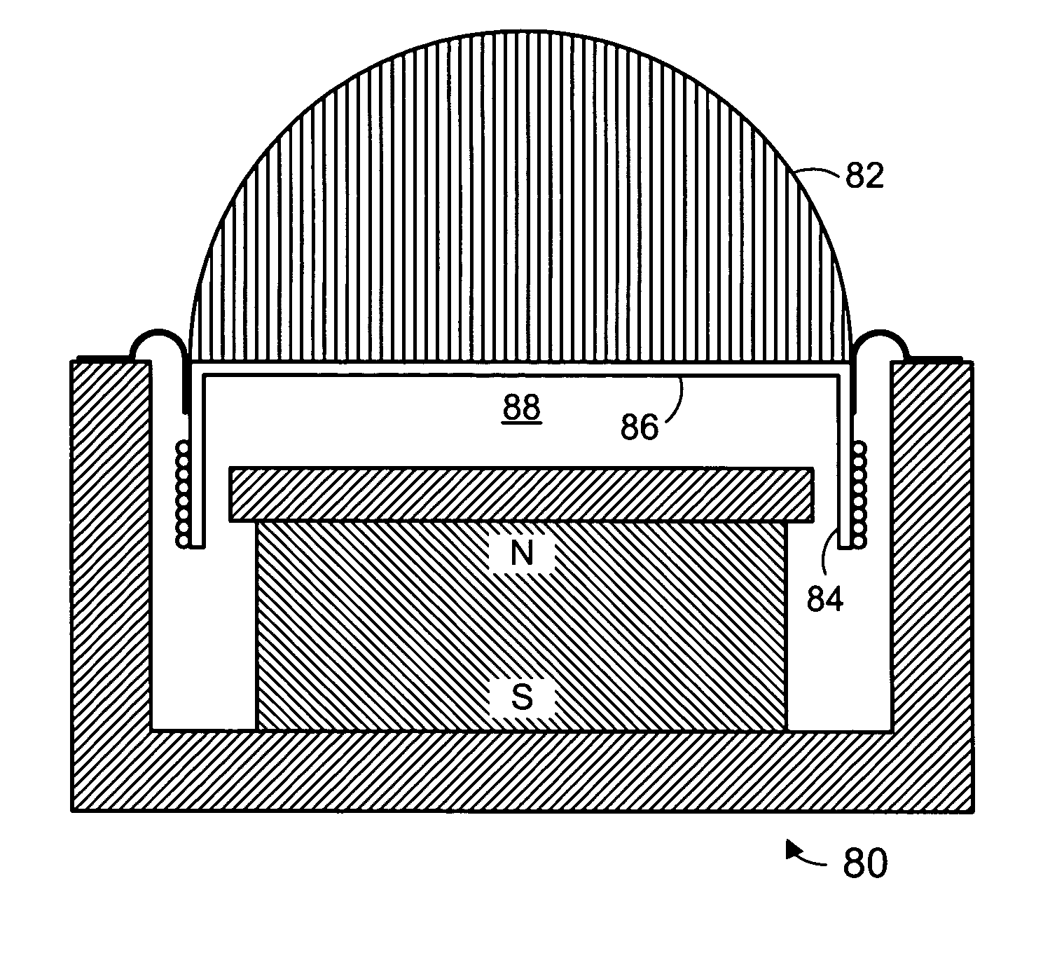
[0030] The invention may be utilized in a variety of magnetic transducer applications, including but not limited to audio speakers, microphones, mechanical position sensors, actuators, and the like. For the sake of convenience, the invention will be described with reference to audio speaker embodiments, but this should be considered illustrative and not limiting.

[0031]FIG. 8 illustrates one embodiment of a tweeter 80 which utilizes a dome 82 according to one embodiment of this invention. The dome is constructed of an ultra lightweight, solid, nanoporous material, such as an aerogel, nanocomposites, or the like, hereinafter collectively referred to as aerogel for convenience. The aerogel dome is coupled to a bobbin 84 which, in some embodiments, may have a closed outer end 86 forming a plate or base to which the aerogel dome is coupled such as with glue. A volume 88 of air is enclosed within the tweeter to provide acoustic loading. The dome may in some embodiments be a hemisphere, a...


PUM


Abstract

An electromagnetic transducer such as a tweeter audio speaker, having a very low density diaphragm constructed of a nanoporous material such as aerogel or the like. The solid aerogel diaphragm has improved rigidity and reduced susceptibility to breakup modes. The aerogel may be provided with a skin of e.g. metal, plastic, or oxide to protect it, and it may be built by filling a conventional cone. The skin may encapsulate part or all of the aerogel body's surface, and it may further encapsulate the bobbin, or even the entire voice coil assembly. The nanoporous material comprises a very large percentage of the diaphragm's overall volume, giving the diaphragm a very low overall mass density with respect to conventional diaphragms. This allows diaphragm configurations, such as solid filled spheres, which have excellent stiffness without suffering from the large mass that such shapes would mandate if constructed from conventional materials.

Description

BACKGROUND OF THE INVENTION [0001] 1. Technical Field of the Invention [0002] This invention relates generally to electromagnetic transducers such as audio speakers, and more specifically to an improved diaphragm having a very low density, such as one formed from a nanoporous material such as aerogel. [0003] 2. Background Art [0004]FIG. 1 illustrates a conventional audio speaker 10 such as is known in the prior art, shown as symmetrical about a center line CL. The speaker includes a motor structure 11 including a magnetic air gap. The motor structure is coupled to a diaphragm assembly 12 by a frame 13. The diaphragm assembly includes a diaphragm 14 which is coupled to the frame by a first suspension component 15 known as a surround. A bobbin or voice coil former 16 is coupled to the diaphragm. An electrically conductive voice coil 17 is coupled to the bobbin and is disposed within the magnetic air gap. The bobbin is coupled to the frame by a second suspension component 18 known as a...

Claims


Application Information

Patent Timeline
Patent Type & Authority Applications(United States)
IPC IPC(8): H04R7/12H04R9/06
CPCH04R7/12H04R7/125H04R2307/029H04R2307/027H04R9/06
Inventor TURNMIRE, PATRICK M.STILES, ENRIQUE M.CALDERWOOD, RICHARD C.
Owner TURNMIRE PATRICK M
Why Eureka
Try Eureka