Systems and methods for viewing an abnormality in different kinds of images

a technology of abnormalities and images, applied in the field of imaging, can solve the problems of difficult spatial co-relationship between the mammogram and the projection mammogram performed using the radiation source and the detector, and the problem of not being very reproducibl

Inactive Publication Date: 2005-04-28
GENERAL ELECTRIC CO
View PDF44 Cites 140 Cited by
  • Summary
  • Abstract
  • Description
  • Claims
  • Application Information

AI Technical Summary

Problems solved by technology

Projection mammography performed using the radiation source and the detector may suffer from certain limitations, such as structured noise from overlying anatomical structures that are in the path of an X-ray beam.
Follow-up ultrasound examinations, however, are not usually conducted on the subject in the same geometry and are thus difficult to spatially co-relate with the mammograms.
Moreover, an ultrasound examination is typically performed by free-hand scanning, which is inherently dependent on the skills of an operator performing the scan, making them not very reproducible.
Furthermore, generally, the ultrasound examination

Method used


Image

  • Systems and methods for viewing an abnormality in different kinds of images
  • Systems and methods for viewing an abnormality in different kinds of images
  • Systems and methods for viewing an abnormality in different kinds of images

Examples


Embodiment Construction

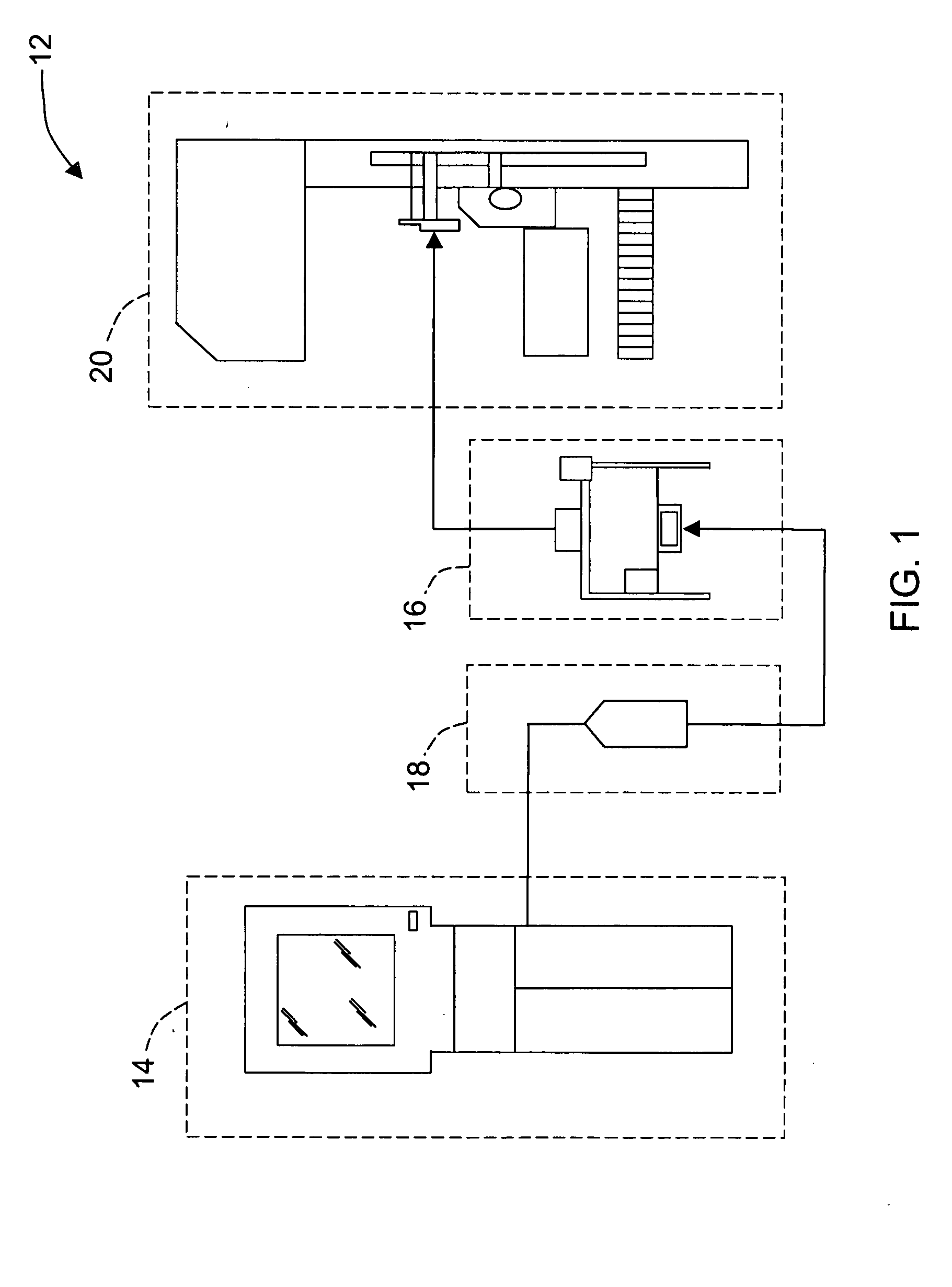
[0028]FIG. 1 is a pictorial view of a medical imaging system 12. In the exemplary embodiment, imaging system 12 includes an ultrasound imaging system 14, a probe mover assembly 16, an ultrasound probe 18, and at least one of an X-ray imaging system and a tomosynthesis imaging system 20. Ultrasound imaging system 14, probe mover assembly 16, ultrasound probe 18, and tomosynthesis imaging system 20 are operationally integrated in imaging system 12. In another embodiment, ultrasound imaging system 14, probe mover assembly 16, ultrasound probe 18, and tomosynthesis imaging system 20 are physically integrated in a unitary imaging system 12.

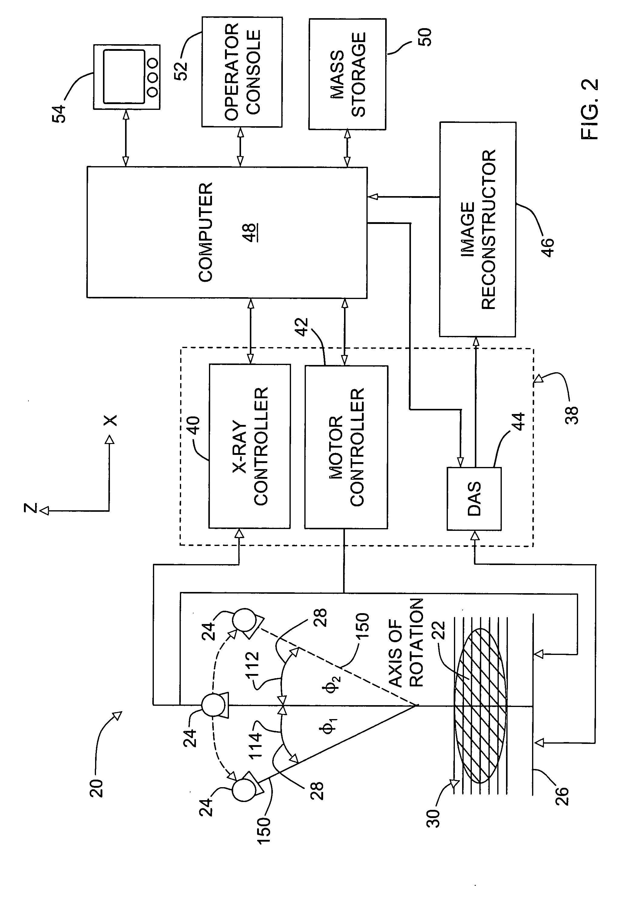
[0029]FIG. 2 is a pictorial view of tomosynthesis imaging system 20. In the exemplary embodiment, tomosynthesis imaging system 20 is used to generate a three-dimensional dataset representative of an imaged object 22, such as a patient's breast. System 20 includes a radiation source 24, such as an X-ray source, and at least one detector array 26 for co...


PUM


Abstract

A method for viewing an abnormality in different kinds of images is described. The method includes scanning an object using a first imaging system to obtain at least a first image of the object, determining coordinates of a region of interest (ROI) visible on the first image, wherein the ROI includes the abnormality, and using the coordinates of the ROI to scan the object with a second imaging system.

Description

STATEMENT REGARDING FEDERALLY SPONSORED RESEARCH & DEVELOPMENT [0001] The government may have rights in this invention pursuant to project number MDA905-00-1-0041 funded by the Office of Naval Research.BACKGROUND OF THE INVENTION [0002] This invention relates generally to imaging and more particularly to systems and methods for viewing an abnormality in different kinds of images. [0003] In at least some known imaging systems, a radiation source projects a cone-shaped beam which passes through a subject, such as a patient, being imaged, and impinges upon a rectangular array of radiation detectors. In at least one known tomosynthesis system, the radiation source rotates with a gantry around a pivot point, and views of the subject may be acquired for different projection angles. [0004] In other known medical imaging systems, ultrasound diagnostic equipment is used to view organs of the subject. Conventional ultrasound diagnostic equipment typically includes an ultrasound probe for tran...

Claims


Application Information

Patent Timeline
IPC IPC(8): A61B5/055A61B6/00A61B6/02A61B6/04A61B8/00A61B8/08G03B42/06G06K9/00G06T7/00
CPCA61B6/4233A61B6/466A61B6/502A61B6/5247A61B8/0825A61B6/545A61B8/5238G06T7/0044A61B6/4417A61B6/04A61B6/5211A61B8/483G06T7/74G16H50/20
Inventor KAPUR, AJAYYAMROM, BORISASTLEY, OLIVER RICHARD
Owner GENERAL ELECTRIC CO
Why Eureka
Try Eureka