
Tightening member

a technology of tightening member and clamping rod, which is applied in the direction of fastening means, screws, fastener tools, etc., can solve the problem of tightness of pressurized medium

Inactive Publication Date: 2005-04-28
VALMET TECH INC
View PDF15 Cites 3 Cited by
  • Summary
  • Abstract
  • Description
  • Claims
  • Application Information

AI Technical Summary

Benefits of technology

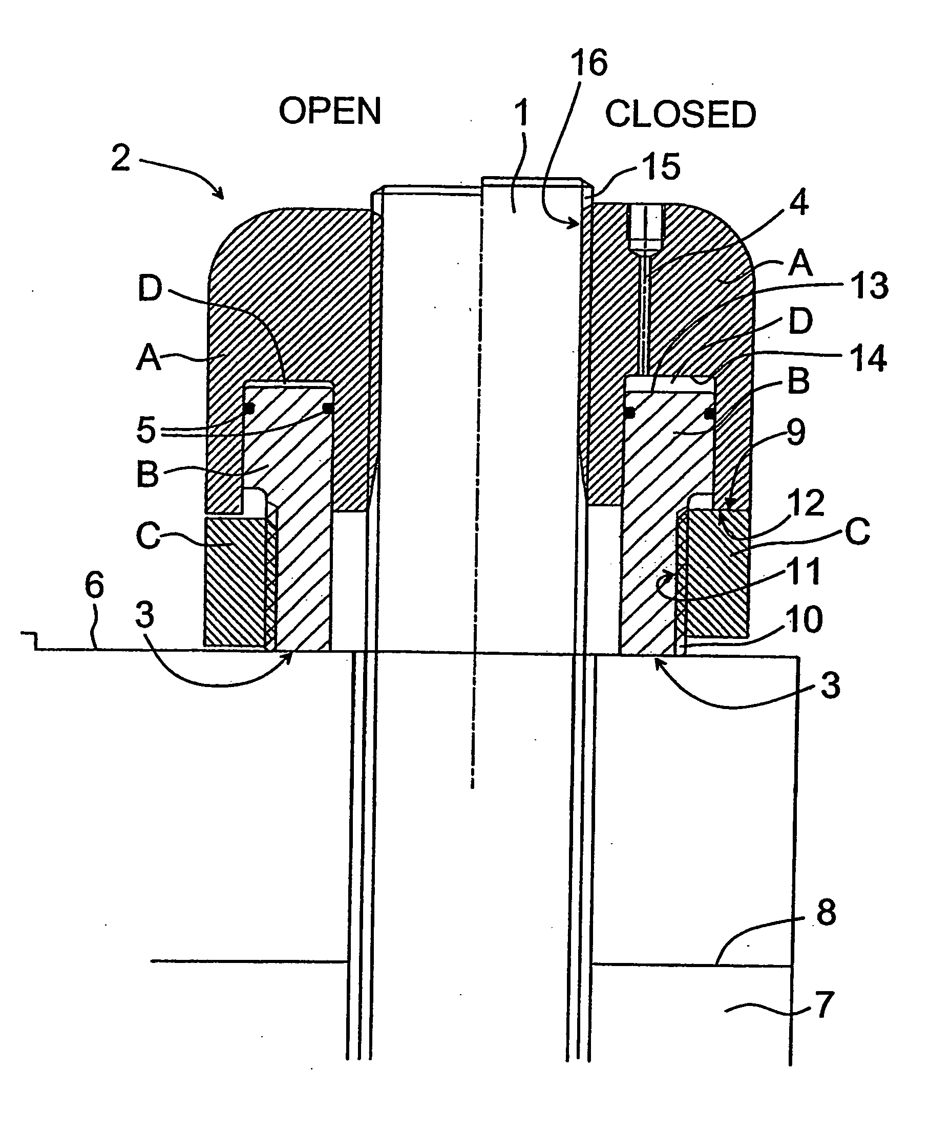
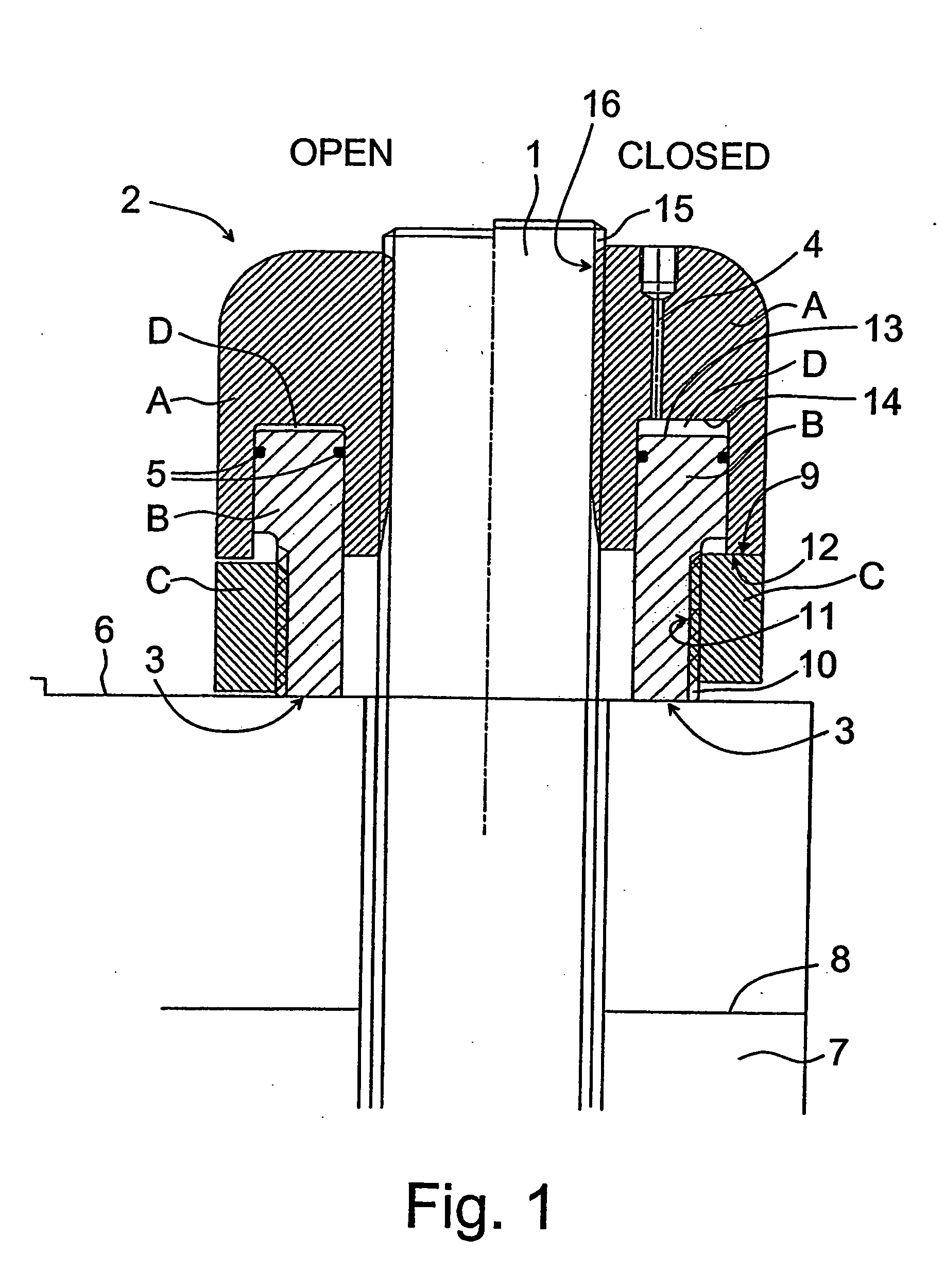
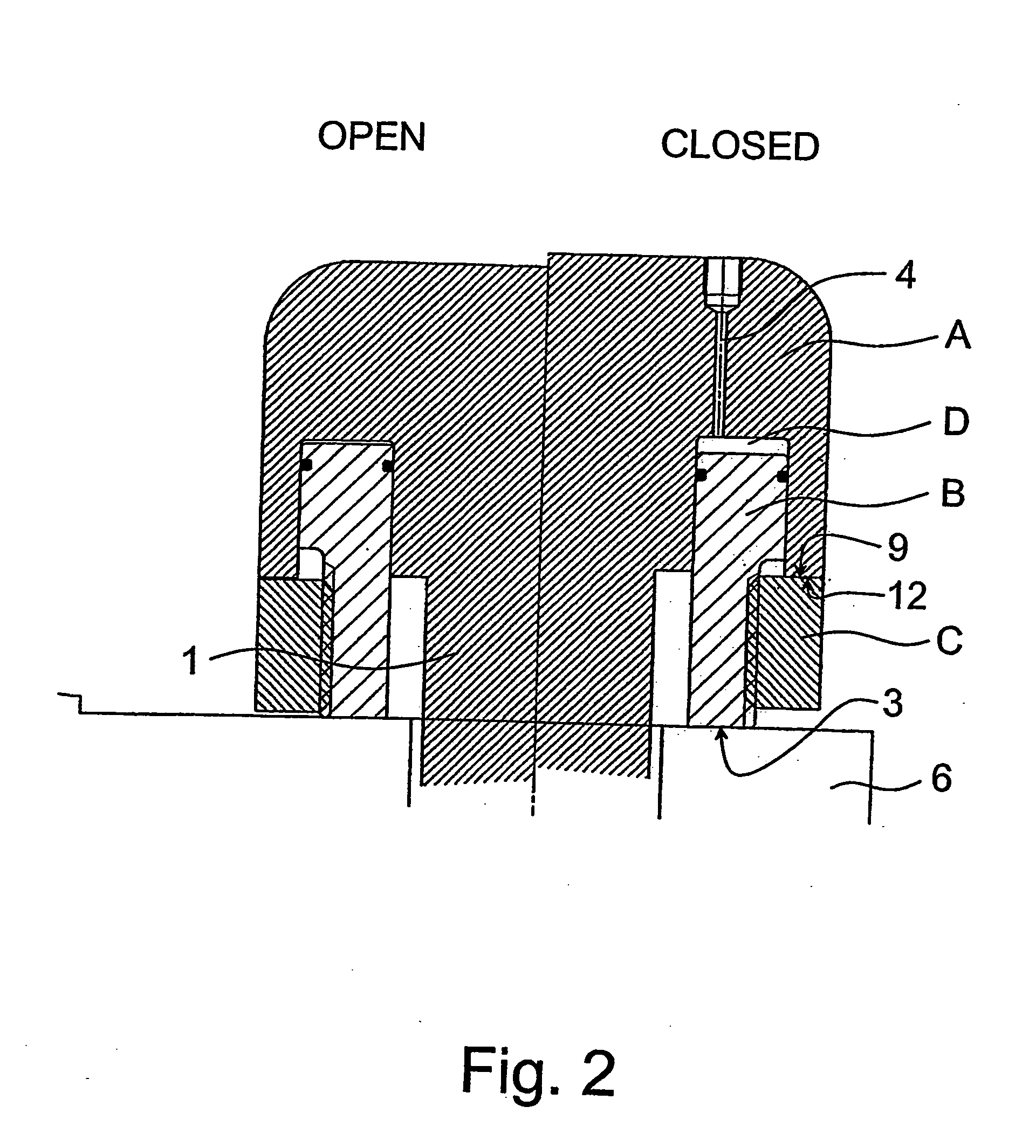
[0009] In the invention, it is possible to achieve, by the method known from the publication GB 2267944, a strain in the fixing means with the same tightening member by which the joint between the two parts is tightened. There is no need for separate pre-tensioning devices or parts to be removed after pre-tensioning. Because the locking part is placed around the second part and underneath the first part (when the first end of the tightening member is considered to be “up”), the whole diameter of the tightening member can still be kept small, without a need to form the inner wall of the pressurized medium chamber thin, which is the result if the recess forming the pressurized medium chamber were transferred close to the fixing means in the radial direction so that the locking part with a reasonable diameter could be placed around the first part.

Problems solved by technology

Although the outer surface of the fixing means, according to the document, supports the inner wall against any further deflection caused by problems of tightness, this thinner inner wall is, however, the weak point in the structure and a potential cause of problems in the tightness for the pressurized medium.

Method used


Image

  • Tightening member
  • Tightening member
  • Tightening member

Examples


Embodiment Construction

[0013]FIG. 1 shows a fixing means 1, which is inserted through two elements to be joined together, for example through bores made in the elements. The fixing means can be an ordinary stud bolt equipped with an outer thread, or the like. FIG. 1 shows the first element 6 to be joined and the second element 7 to be joined, and a joint plane 8 therebetween, through which the fixing means 1 is inserted. The elements 6, 7 can be joined together, for example, at their flange-like protrusions, through which the bores have been made. The elements may be some machine parts. At the opposite end of the fixing means 1, there is a part which abuts the second element to be joined and which at that point fixes the fixing means to be immobile in its longitudinal direction. This part, which may be an ordinary nut or a protrusion integrated in the fixing means, is not shown in more detail.

[0014] The tensioning means 2 screwed around the fixing means 1, close to its outermost end, comprises a first pa...


PUM


Abstract

A hydraulic nut having a first part connected around the first end of a fixing member the first part having an annular recess which opens to receive a second part forming an annular member which fits within the annular recess, wherein a pressurized medium chamber is defined between the second part and the annular recess. The second part has an annular portion which extends longitudinally away from the first part. The annular portion has an outer surface which is spaced radially inwardly to form a locking part recess. A locking part is placed within the locking part recess, and has an inner diameter which is threadedly engaged with the second part outer surface. The locking part has a surface facing the first part first surface, and movable by the threaded engagement with the second part to an abutment with the first part first surface.

Description

CROSS REFERENCES TO RELATED APPLICATIONS [0001] This application is a U.S. National Stage application of International application PCT / FI03 / 00090, which was filed on Feb. 5, 2003, and claims priority on Finnish Application No. 20020258, which was filed on Feb. 7, 2002. STATEMENT AS TO RIGHTS TO INVENTIONS MADE UNDER FEDERALLY SPONSORED RESEARCH AND DEVELOPMENT [0002] Not applicable. BACKGROUND OF THE INVENTION [0003] Pre-tensionable bolts are previously known, which can be provided with a strain by means of a pressurized medium chamber arranged at one end of the bolt, after which it is possible to tighten a tightening member at the opposite end of the bolt. Such arrangements, for example, in connection with bolts intended for joining two elements, are presented e.g. in GB patent 1 382 192 and in DE publication 24 58 810. This latter publication also presents a traction means which is screwed around one end of a fixing means and comprises two parts, between which there is a space whe...

Claims


Application Information

Patent Timeline
Patent Type & Authority Applications(United States)
IPC IPC(8): F16B31/04
CPCF16B31/043Y10S411/916Y10S411/917Y10S411/915
Inventor KAMPPILA, KAUKO
Owner VALMET TECH INC
Learn More