
Foldable die cut self-adhesive label sheet for labeling cd-roms

a self-adhesive, label sheet technology, applied in the field of label sheets, can solve the problems of requiring a fair amount of manual dexterity, difficult and time-consuming operation, and difficulty in separating labels and liner sheets, and achieves the effects of reducing the number of labels

Active Publication Date: 2005-04-28
CCL LABEL INC
View PDF70 Cites 46 Cited by
  • Summary
  • Abstract
  • Description
  • Claims
  • Application Information

AI Technical Summary

Benefits of technology

The present invention provides a label sheet assembly that can be easily fed through a printer and torn open along weakened separation lines to remove individual labels. The assembly includes a matrix and a release liner with cuts and ties that allow for easy tearing. The size and ratio of cuts and ties are chosen so that the assembly is strong enough to be fed through a printer but weak enough to allow for easy tearing without other mechanical preparation of the label sheet. The separation lines are positioned close enough to the edge of the label sheet to allow for easy tearing, but far enough to prevent the label sheet from sticking to surfaces. The technical effect of the invention is to provide a convenient and efficient way to remove labels from a label sheet assembly.

Problems solved by technology

The technical problem addressed in this patent text relates to improving the efficiency and ease of removable address labels used for printing numerous addresses or other information on small sheets. Current methods require significant effort and skill, resulting in difficulty and time consumption when applying the labels. Additionally, certain types of label designs may result in difficulties during die cutting and separation from the liner. The patent proposes solutions through the development of label strips or webs designed for automatic separation and placement onto various surfaces.

Method used


Image

  • Foldable die cut self-adhesive label sheet for labeling cd-roms
  • Foldable die cut self-adhesive label sheet for labeling cd-roms
  • Foldable die cut self-adhesive label sheet for labeling cd-roms

Examples


first embodiment

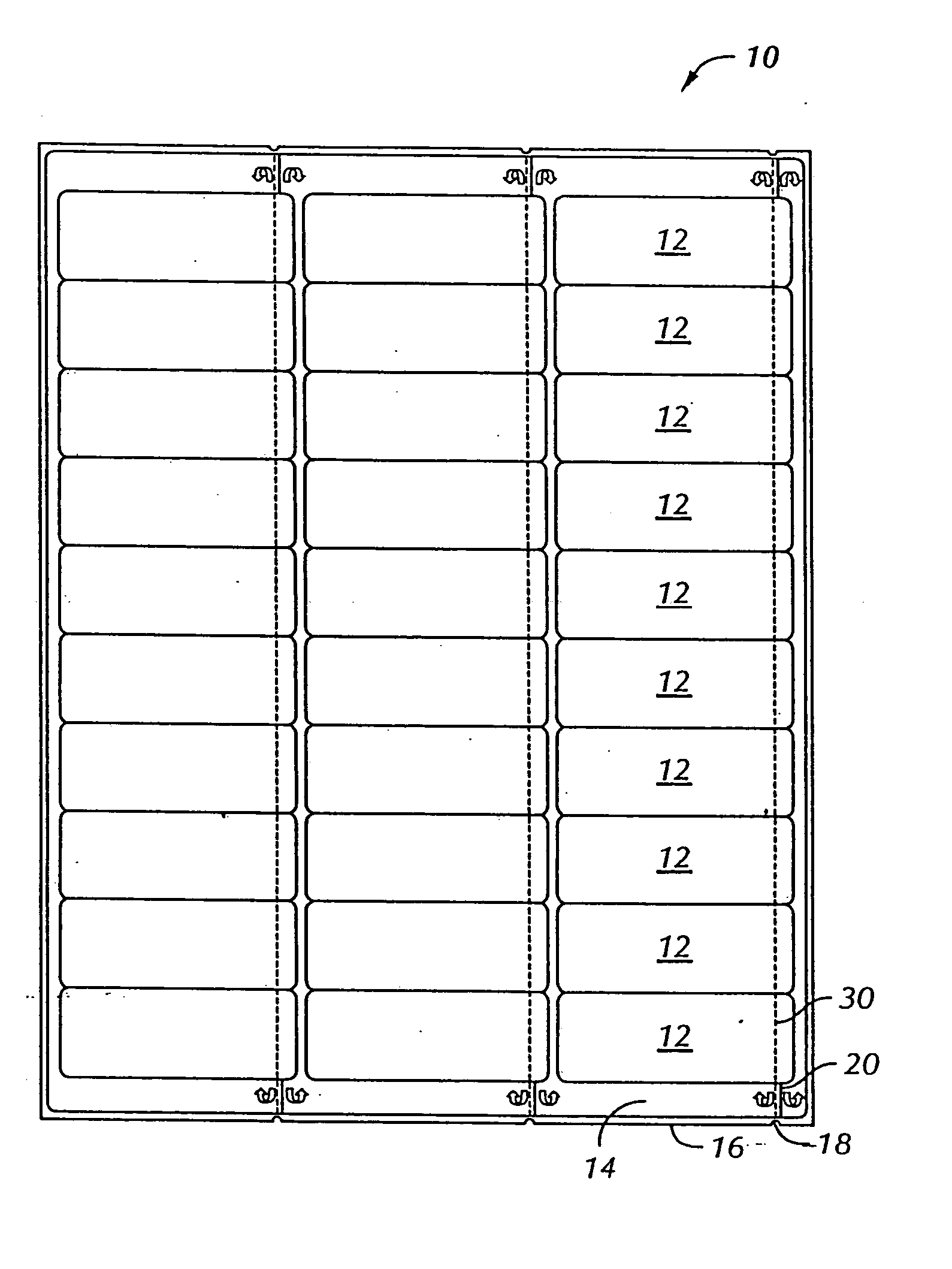
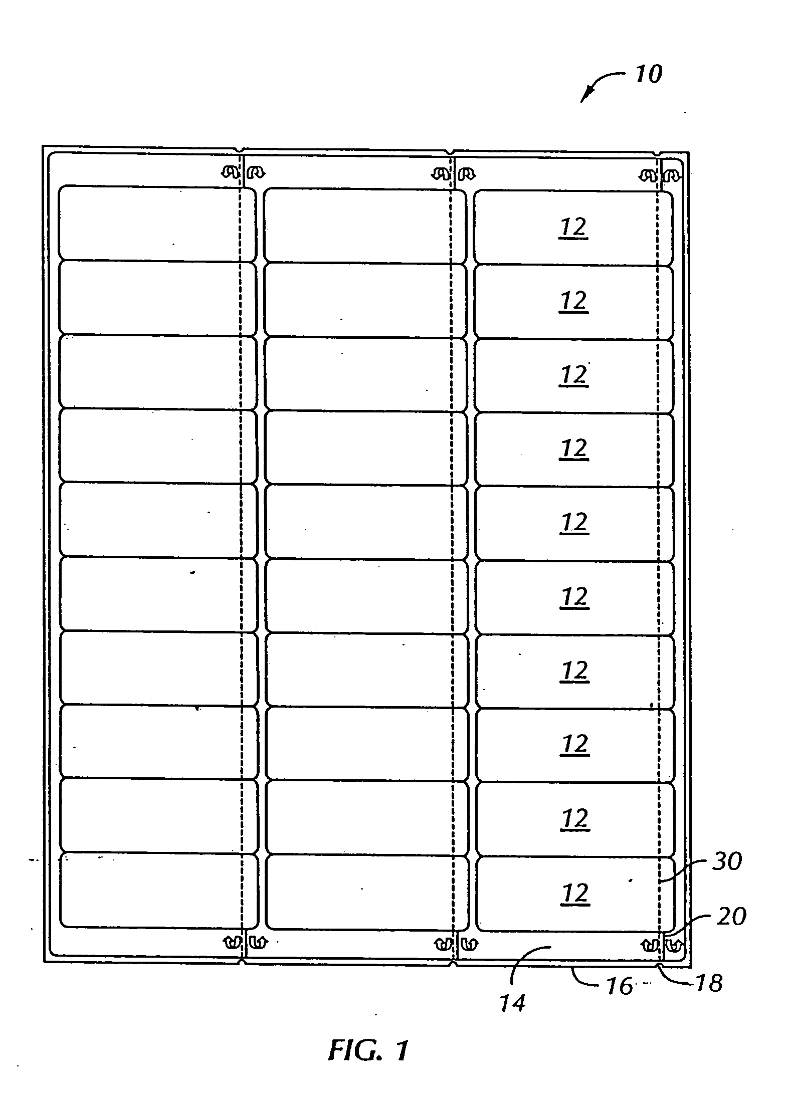
[0017]FIG. 1 shows label sheet assembly 10 in which the labels can be easily peeled according to the present invention. The label assembly 10 is preferably of an overall standard size such as 8½ inches by 11 inches, or A4 (approximately 21 cm×29.7 cm), or 4 inches by 6 inches, or other size compatible with standard printers used with personal computers. Assembly 10 includes a release liner sheet or simply release liner 16 with a sheet of facestock material releasably adhered thereto via a pressure sensitive adhesive. The release liner 16 is coated with a thin layer of release material such as silicone, or is otherwise constructed or treated such that the labels can be easily removed therefrom. The sheet of facestock material comprises a generally rectangular sheet of paper or film facestock with a plurality of labels 12 formed therein such as by die cutting. The section of the facestock sheet not used for labels constitutes the border or matrix 14. In the figure the facestock sheet ...

third embodiment

[0026]FIG. 8 shows a third embodiment similar to the embodiment shown in FIG. 1, except that the label assembly does not include notches.

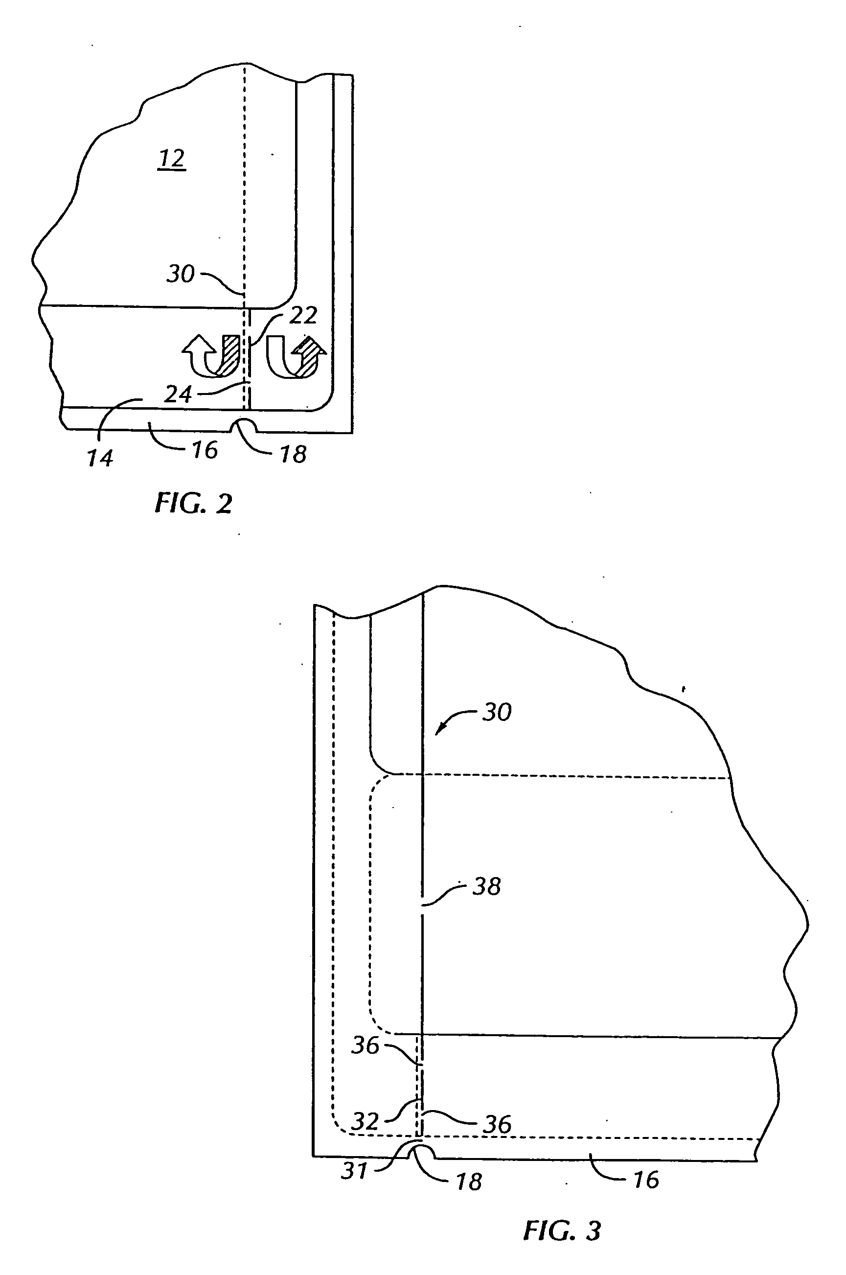
[0027] As shown in FIGS. 1 and 2, the facestock material is slightly smaller than the liner 16 such that matrix 14 does not extend to the edge of the label assembly. If the facestock were to extend to the edge of the label sheet, it would be desirable to form notch 18 in both matrix 14 and liner 16.

[0028] In yet another possible embodiment, the label assembly would not even include a matrix bordering the labels. In FIG. 1, for example, matrix 14 could be entirely stripped from the label sheet before the product is sold. Alternatively, the entire sheet of facestock material could be die cut such that the entirety of the facestock material formed labels. The facestock material could either take up the same amount of facestock area shown in FIG. 1, or a significantly smaller area. Regardless of how the facestock material were constructed, shaped, and...


PUM

PropertyMeasurementUnit
Lengthaaaaaaaaaa
Lengthaaaaaaaaaa
Fractionaaaaaaaaaa

Abstract

A label sheet (1) having a release liner (16) and a column of labels (12) releasably adhered thereto is modified to allow easy removal of the labels. The liner has a weakened separation line (30) formed by cuts and ties running underneath a column of labels near the edge of the labels, and notches (18) at the top and bottom of the sheet aligned with the cuts and ties. A matrix (14) surrounding the labels, if present, also has cuts and ties, with the cuts and ties in the matrix parallel to and slightly offset from the cuts and ties in the liner. The separation lines are strong enough that the label sheet can be fed through a printer, yet weak enough that a user can tear off the liner and matrix along the separation lines, thus leaving a minor edge of a column of labels exposed for easy removal from the label sheet.

Description


Claims


Application Information

Patent Timeline
Owner CCL LABEL INC
Learn More