Power transmission system for vehicle

a transmission system and vehicle technology, applied in mechanical equipment, transportation and packaging, gearing, etc., can solve the problems of increasing cost, affecting the performance of other parts, and the inability to keep the performance constant for the variety of oil, so as to minimize the adverse effects of abraded powder

Inactive Publication Date: 2005-04-28
TOYODA MASCH WORKS LTD
View PDF6 Cites 4 Cited by
  • Summary
  • Abstract
  • Description
  • Claims
  • Application Information

AI Technical Summary

Benefits of technology

[0009] Accordingly, it is an object of the present invention to provide a power transmission system for vehicle in which the design of a differential gearing need not be changed for a different type of the gear box, allowing a common specification to be used for various gear boxes. It is another object of the present invention to provide a power transmission system for vehicle which assures a given performance of a differential gearing without being influenced by an oil used. It is a further object of the present invention to provide a power transmission system for vehicle which is capable of minimizing adverse influences of abraded powder.

Problems solved by technology

In the conventional arrangement mentioned above, the differential gearing 102 is disposed within the gear box 106, and accordingly, it is necessary to design the differential gearing depending on the structure of the gear box 106, resulting in an increased cost.
The differential action limiting function is influenced by an oil (gear oil, ATF of CVT oil) within the gear box 106, presenting a problem that the performance cannot be kept constant for the variety of the oil.
In addition, if ATF or CVT oil is used in the gear box 106, there is a likelihood that abraded powder may be produced, presenting a problem that such an abraded powder may have an adverse influence on other parts.

Method used


Image

  • Power transmission system for vehicle
  • Power transmission system for vehicle
  • Power transmission system for vehicle

Examples


second embodiment

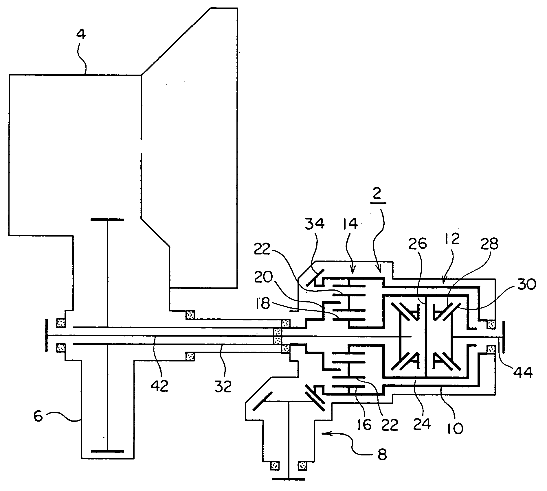
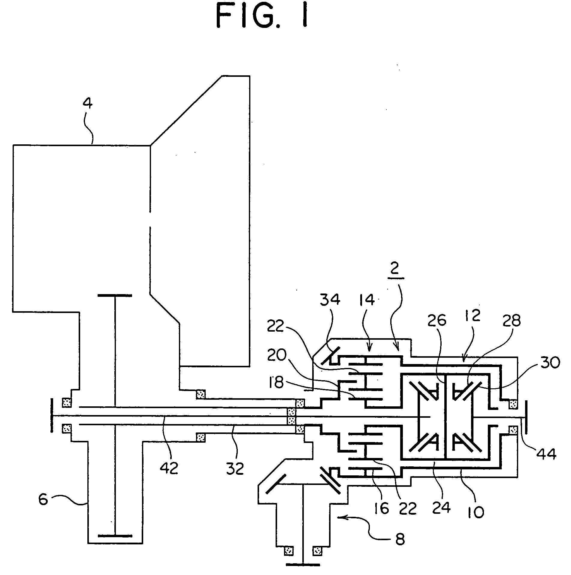
[0028] In the second embodiment, an output from the differential gearing 2 is transmitted to PTO 8 through a countershaft 38. Specifically, an output gear 10Ba which is formed around the outer periphery of the housing 10 of a differential gearing 2 is in meshing engagement with a gear 38a mounted on the countershaft 38 of PTO 8, whereby an output from the internal gear 16 of the center differential unit of planetary gear type 14 is transmitted to the PTO 8 through a bevel gear 38b on the countershaft 38.

first embodiment

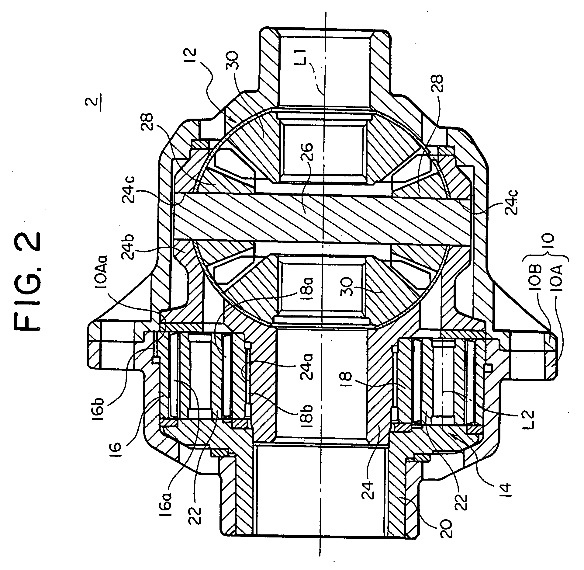
[0029] Again, the differential gearing for vehicle 2 is disposed within the PTO 8 rather than within the gear box 6 of the transmission 4 in distinction to the prior art, achieving similar functions and effects as achieved in the While the twin differential unit described in the above embodiments comprises an integral assembly of the front differential unit 12 of bevel gear type and the center differential unit 14 of planetary gear type, it should be understood that the present invention is not limited to such configuration, but that the twin differential unit may comprise an integral assembly of a center differential unit having a different construction and another differential unit for left and right wheels of a different construction.


PUM


Abstract

A differential gearing 2 of twin differential type including a center differential unit 14 of planetary gear type and a front differential unit 12 of bevel gear type which are received within a housing 10 is separated from a gear box 6 of a transmission 4, and is disposed within PTO (power transfer off) 8. A common specification can be used for the twin differential unit, and influences by the oil variety can be avoided, assuring a given performance in any application.

Description

CROSS-REFERENCE TO RELATED APPLICATIONS [0001] This application is based upon and claims priority under 35 USC 119 to Japanese Patent Application No. 2003-367567 filed on Oct. 28, 2003, entire contents of which are incorporated herein by reference. BACKGROUND OF THE INVENTION AND RELATED ART STATEMENT [0002] The present invention relates to a power transmission system for vehicle, in particular, to a power transmission system for vehicle having a differential gearing formed by a twin differential unit in which a center differential unit and another differential unit associated with left and right wheels such as a center differential unit of planetary gear type and a front differential unit of bevel gear type are constructed together in an integral manner. [0003] As shown in FIGS. 5 and 6, a conventional power transmission system for vehicle includes a differential gearing 102 for vehicle of a twin differential type having an integral construction of a front differential unit 112 of ...

Claims


Application Information

Patent Timeline
Patent Type & Authority Applications(United States)
IPC IPC(8): F16H1/28B60K17/16B60K17/28F16H48/05F16H48/08F16H48/38F16H48/40
CPCB60K17/16B60K17/28F16H2048/082F16H48/10F16H48/11F16H48/08B60K17/346
Inventor NAKAJIMA, SINICHIRONISHIJI, MAKOTO
Owner TOYODA MASCH WORKS LTD
Why Eureka
Try Eureka