Method of manufacturing sputter targets with internal cooling channels

a technology of internal cooling channel and sputter target, which is applied in the direction of manufacturing tools, forging/pressing/hammering apparatus, transportation and packaging, etc., can solve the problems of high sputtering rate, bowing or bending, and causing leakage, so as to reduce bowing or bending, the effect of reducing the thermal energy of the sputter target assembly and reducing the electrical conductivity

Inactive Publication Date: 2005-05-05
TOSOH SMD
View PDF24 Cites 32 Cited by
  • Summary
  • Abstract
  • Description
  • Claims
  • Application Information

AI Technical Summary

Benefits of technology

[0009] The bonding methods of the present invention allow target and backing plate assembly bonding with the assembly exhibiting reduced bowing or bending. Additionally, the low temperature pressure consolidation methods of the present invention do not cause undesirable grain growth of the target material or deformation of the cooling channels during consolidation of the target material with the backing plate material.
[0010] As a result, the sputter target assemblies in accordance with the present invention are able to utilize backing plate materials having higher thermal and lower electrical conductivity than the conventional backing plate materials normally compatible with a specific target material. The reduction of bowing and bending is especially beneficial in sputter target assemblies with internal cooling channels. The opportunity for leakage is greatly reduced by use of the low temperature pressure consolidation methods in accordance with the present invention.
[0011] A second objective of the present invention provides for formation of the cooling channels is such a way that the cooling channel formation also results in an interference friction fit bond between the target material and the backing plate material. Thereby, the time and steps necessary for sputter target assembly production are greatly reduced.

Problems solved by technology

Magnetron sputtering imposes considerable thermal energy upon the sputter target assembly, especially within the concentrated annular region of the target raceway.
These bonding methods typically involve imposition of high temperatures.
Sputter target assemblies bonded by these methods can bow or bend at high sputtering rates, especially when a large difference exists between the coefficients of thermal expansion for the target material and backing plate material.
In sputter target assemblies with internal cooling channels, bowing and bending induces leakage; the typical bonding methods, described above, tend to deform, or otherwise partially constrict, the cooling channels.
Additionally, known bonding techniques, as discussed above, result in undesirable grain growth in the target material or the resulting bond cannot withstand the stresses imposed by high sputtering rates.

Method used


Image

  • Method of manufacturing sputter targets with internal cooling channels
  • Method of manufacturing sputter targets with internal cooling channels
  • Method of manufacturing sputter targets with internal cooling channels

Examples


second embodiment

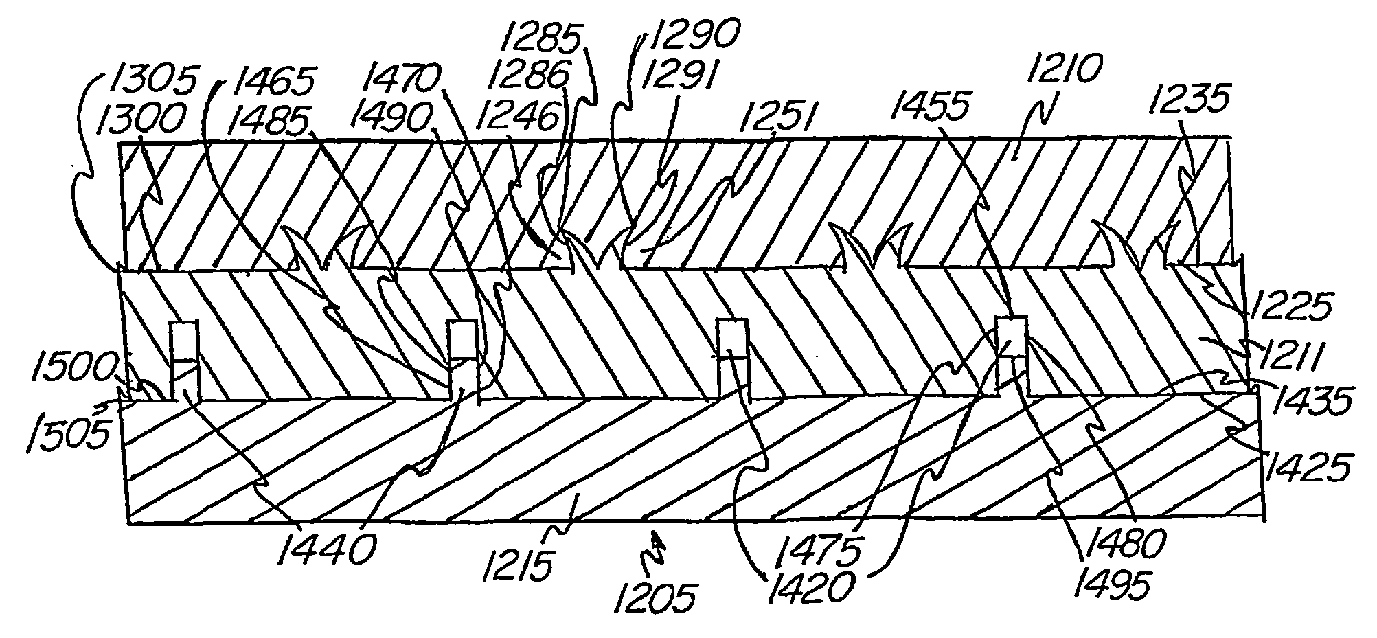
[0043] Turning now to FIG. 8, there is shown a sputter target assembly 205, in accordance with the present invention, subsequent to the target material 210 and backing plate material 215 being consolidated. The low temperature pressure consolidation method as discussed above with regard to the preferred embodiment is preferred. As a result of the low temperature pressure consolidation the protruding portions 240 penetrate into the target material 210 and disrupt the oxide film that may exist along the mating surface 235, thereby, promoting a metal to metal cold diffusion type bond. The tips 285, 290 deform and fold back toward the mating surfaces 225, 235, providing a physical locking mechanism, or “ZIP bond,” between the target material 210 and backing plate material 215.

[0044] With further reference to FIG. 8, the deformed edges 286, 291 of the “M” shaped protruding portions 240 are bent toward the mating surfaces 225, 235 as a result of the low temperature pressure consolidation....

third embodiment

[0050] The assembly 405 is then subjected to low temperature pressure consolidation as with the preceding embodiments. In this third embodiment, the protruding portions 440 are received within receptacles 496 through openings 498. The sides 485, 490 of the protruding portions 440 cooperate with the sidewalls 497, 499 of the receptacles 496, respectively, to result in a friction fit bond between the target material 410 and the backing plate material 415.

[0051] With further reference to FIG. 10, it can be seen that a portion of the mating surface 425 cooperates with the sidewalls 445, 450 and bottom portion 455 of the grooves 430 to form the cooling channels 420. The opening 460 is thereby sealed.

[0052] The low temperature annealing step, as described above in regard to the preferred embodiment, will induce improved bonding. As with the preferred embodiment, it is preferable to employ a protruding portion thickness greater than the groove width, thereby, providing for an interference...

sixth embodiment

[0073] In this sixth embodiment, the lower portions 1075, 1080 and bottom portion 1055 of the grooves 1030 cooperate with the end portion 1095 of the protruding portions 1040 to define the cooling channels 1020. As can be seen in FIG. 16, the distance from the mating surface 1025 to the bottom portion 1055 of the grooves 1030, the “groove depth,” is greater than the distance from the mating surface 1035 to the end portion 1095 of the protruding portions 1040, the “protruding portion length.” The cross section of the cooling channels 1020 can be increase, or decreased, by varying the groove width or by varying the differential in the groove depth with respect to the protruding portion length.


PUM

PropertyMeasurementUnit
temperatureaaaaaaaaaa
temperaturesaaaaaaaaaa
temperatureaaaaaaaaaa

Abstract

The present invention pertains to low temperature pressure consolidation methods which provide for bonding of target material (10) to the backing plate material (15) capable of withstanding the stresses imposed by high sputtering rates. The sputter target assemblies (5) in accordance with the present invention are preferably comprised of target materials (10) and backing plate materials (15) having dissimilar thermal expansion coefficients and incorporate internal cooling channels (20). In the preferred embodiment, the resulting bond and the formation of the cooling channels (20) are cooperative.

Description

CROSS-REFERENCE TO RELATED APPLICATION [0001] This application is a divisional application of U.S. patent application Ser. No. 10 / 344,782 filed on Feb. 13, 2003 and claims the priority filing benefit of International PCT / US01 / 28411 filed Sep. 11, 2001 and U.S. Provisional Application Ser. No. 60 / 231,917 filed Sep. 11, 2000.FIELD OF THE INVENTION [0002] The present invention relates to sputter target assemblies for use within sputtering systems. More specifically, the present invention pertains to sputter target assemblies with internal cooling channels which include a target material bonded, by low temperature pressure consolidation, to a backing plate material. BACKGROUND OF THE INVENTION [0003] Cathodic sputtering is widely used for the deposition of thin films, or layers, of material onto desired substrates. The sputtering process employs gas ion bombardment of a target material having a face formed of a material that is to be deposited as a thin film, or layer, on the given subs...

Claims


Application Information

Patent Timeline
Patent Type & Authority Applications(United States)
IPC IPC(8): B21K25/00B23K20/02C23C14/34H01J37/34
CPCB21K25/00B23K20/02B23K20/023Y10T428/24298H01J37/3435H01J37/3497Y10T428/24744C23C14/3407Y10T428/24996Y10T428/249974Y10T428/249981C23C14/35
Inventor IVANOV, EUGENE Y.
Owner TOSOH SMD
Why Eureka
Try Eureka