Saw blade for a machine tool

A technology for machine tools and saw blades, applied in the field of rotary oscillating saw blades, to achieve the effects of improving chip export, uniform load and prolonging service life

Active Publication Date: 2014-04-30
ROBERT BOSCH GMBH
View PDF6 Cites 12 Cited by
  • Summary
  • Abstract
  • Description
  • Claims
  • Application Information

AI Technical Summary

Problems solved by technology

Although the part-round design of the cutting edge results in a uniform loading of the cutting teeth, chips generated during machining are not optimally evacuated from the cutting area when the direction of rotation changes

Method used


Image

  • Saw blade for a machine tool
  • Saw blade for a machine tool

Examples


Embodiment Construction

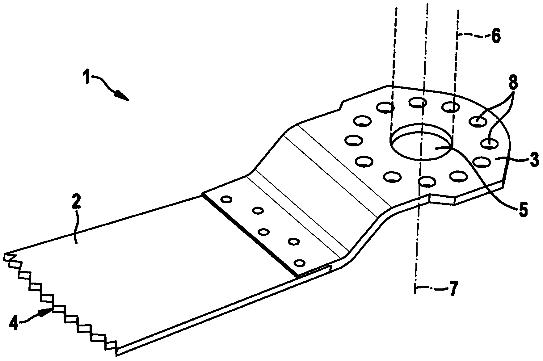
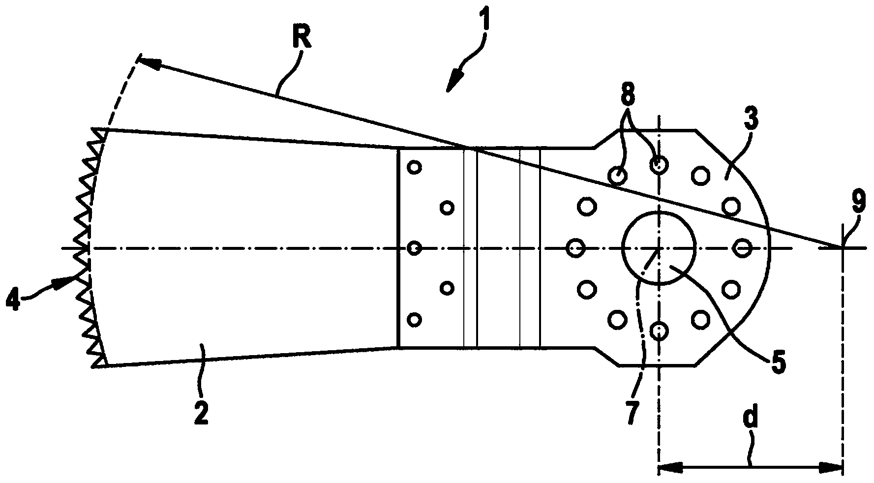
[0019] exist figure 1 shows a saw blade 1 embodied as a sinker saw blade for a hand tool with a rotary oscillating drive. The saw blade 1 comprises: a main blade 2, which is embodied in the shape of a plate with an approximately rectangular, if necessary slightly trapezoidal, geometry; The tool axis 6 is connected. The front edge of the main plate 2 facing away from the fastening section 3 is designed as a cutting edge 4 with cutting teeth.

[0020] A central fastening recess 5 for receiving the tool shaft 6 is introduced into the substantially disk-shaped fastening section 3 . The fastening is carried out by means of a suitable fastening device, wherein in the fastening section 3 for torque transmission, a snap-in opening 8 arranged around the fastening recess 5 is introduced annularly, the catch of the fastening device in the mounted state The locking projection protrudes into the locking opening in order to transmit the torque from the tool shaft to the saw blade 1 .

...


PUM


Abstract

A saw blade (1) has a blade base (2) with an arcuate cutting edge (4), which is curved to a lesser extent than a circular arc with a radius that corresponds to the distance between the axis of rotation of the saw blade and the cutting edge (4).

Description

technical field [0001] The invention relates to a saw blade according to the preamble of claim 1 , in particular a rotary oscillating saw blade for a power tool. Background technique [0002] A saw blade for a saw with a rotationally oscillating drive movement is known from DE 20308797 U1. The saw blade has an approximately rectangular main piece which is formed in one piece with a fastening section in which a recess is introduced for receiving a tool shaft of the saw. On the side facing away from the recess, the main plate is provided with a cutting edge which is used for machining the workpiece and which is provided as a straight edge with cutting teeth. [0003] The following problem can arise with straight cutting edges: Corner areas can become lodged in the material of the workpiece during machining. When the direction of rotation is reversed, only the corner regions are in contact with the workpiece, so that the cutting edge is subjected to an uneven load. [0004] ...

Claims


Application Information

Patent Timeline
Patent Type & Authority Applications(China)
IPC IPC(8): B23D61/00
CPCB23D61/006Y10T83/929Y10T83/9319Y10T83/9454Y10T83/9457B23D51/00B27B19/006
Inventor M·博齐克
Owner ROBERT BOSCH GMBH
Why Eureka
Try Eureka