Stage structure in bonding machine and method for controlling the same

Inactive Publication Date: 2005-05-05
LG DISPLAY CO LTD
View PDF4 Cites 5 Cited by
  • Summary
  • Abstract
  • Description
  • Claims
  • Application Information

AI Technical Summary

Benefits of technology

[0032] An advantage of the present invention is to provide a stage structure in a bonding machine for fabricating a liquid crystal display (LCD), which can provide a bonding machine which has a size optimized to an overall layout, movement ranges, and directions of stages simplified for smooth alignment of the substrates. The time period required for fabrication of one LCD is shortened for smooth process design in relation to other processes, and which can separate the substrates from the stage more smoothly in releasing the electro-static adsorption after the electro-static adsorption, and a method for fabricating a bonding machine is provided.

Problems solved by technology

Despite the various technical developments in the LCD for serving as a display in different fields, the efforts for enhancing a picture quality of the LCD as a display are inconsistent with the features and advantages of the LCD in many aspects.
However, the foregoing related art assembler (bonding machine) has the following problems.
First, because the related art bonding machine has a system in which the sealant coating and the liquid crystal dropping are made on the substrate having the thin film transistors formed thereon, and the substrate having the color filter layer formed thereon, the related art bonding machine becomes bulky by the parts for carrying out the sealant coating and the liquid crystal dropping.
Particularly, the bonding machine for large sized LCDs required recently becomes more bulky, such that fabrication of the large sized LCDs is unfavorable.
Second, if the sealing in the coupling between the lower chamber unit and the upper chamber unit is not perfect, the substrates may be damaged during the bonding, and the bonding may be defective due to infiltration of air through a leakage part.
Accordingly, parts for prevention of air leakage is additionally required in the vacuum state, and the required accuracy causes difficulty.
Third, the electro-static chuck of two plate electrodes, absorbing the substrate by having voltages of different poles applied thereto, are likely to drop the substrate as the electro-static absorbing force is not adequate.
Moreover, the large sized glass substrate cannot be adsorbed.
Fourth, the alignment of the substrates by moving the lower chamber unit in a lateral direction in bonding the substrates is very difficult, which increases a time period required for the entire fabrication.
That is, because there are many movements required for the fabrication, such as the movement of the lower chamber unit to a location for dropping the liquid crystal or coating the sealant onto a substrate held at the lower stage, and the returning of the lower chamber to a location for bonding the substrates again when above process is finished, accuracy of the substrate alignment cannot be secured.

Method used


Image

  • Stage structure in bonding machine and method for controlling the same
  • Stage structure in bonding machine and method for controlling the same
  • Stage structure in bonding machine and method for controlling the same

Examples


Embodiment Construction

[0068] Reference will now be made in detail to embodiments of the present invention, examples of which are illustrated in the accompanying drawings.

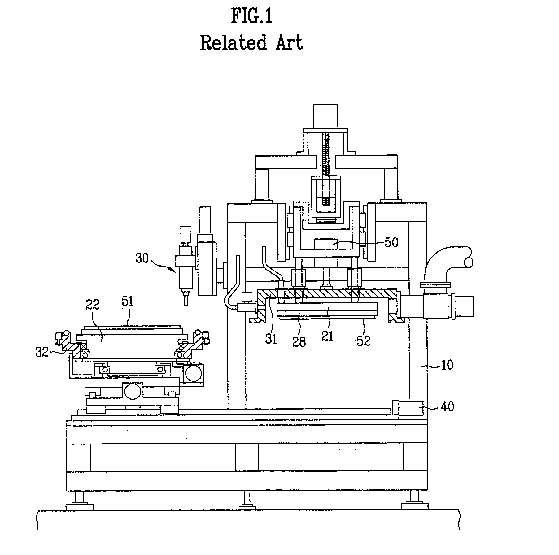
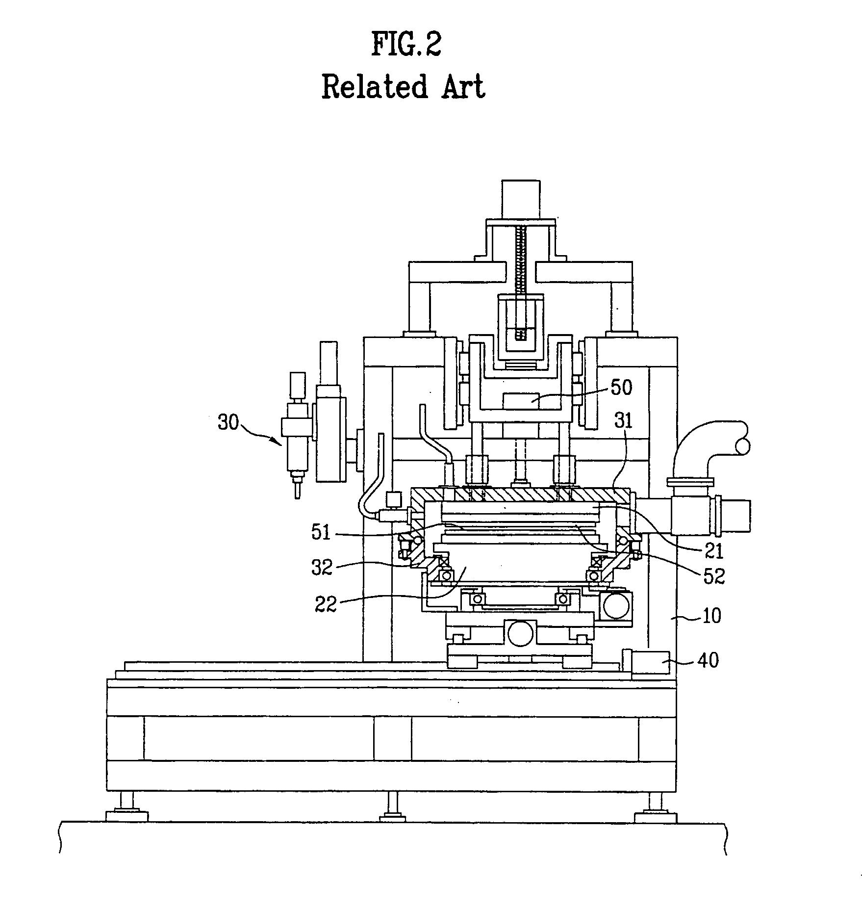
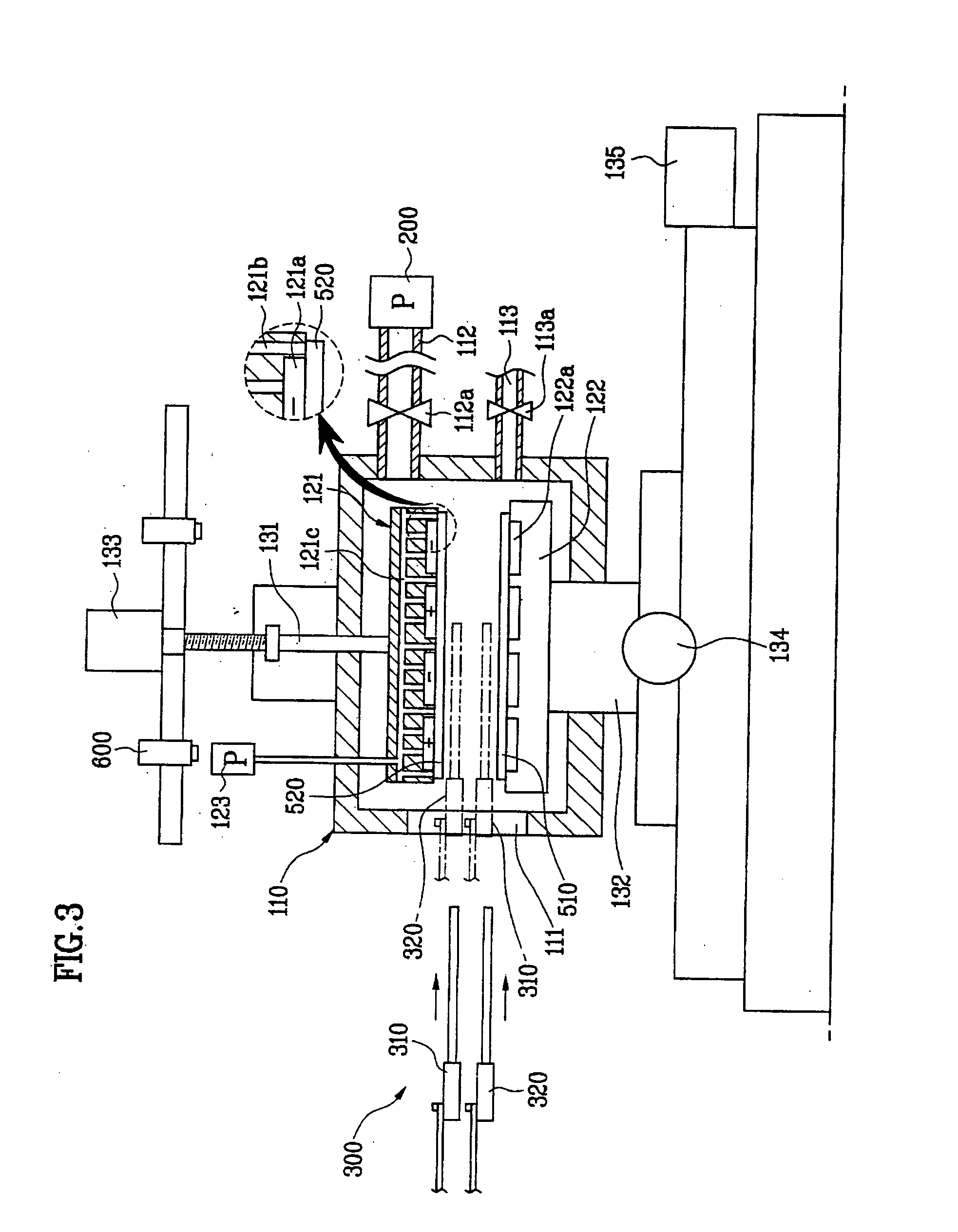
[0069]FIG. 3 illustrates a bonding machine for fabricating a liquid crystal device (LCD) having a liquid crystal dropping method applied thereto in accordance with an embodiment of the present invention, schematically.

[0070] It is suggested that the bonding machine of the present invention includes a bonding chamber 110, a stage part, a stage moving device (unlabeled), an evacuation device (unlabeled), a vent device (unlabeled), and a loader part 300.

[0071] The bonding chamber 110 includes an inside space for carrying out bonding by pressing the substrates to each other, and bonding by using a pressure difference in succession by selectively making the space a vacuum state, or an atmospheric state, and an opening 111 in one side for moving the substrate in or out.

[0072] The bonding chamber 110 further includes an air extraction tube ...


PUM

PropertyMeasurementUnit
Pressureaaaaaaaaaa
Structureaaaaaaaaaa
Electric potential / voltageaaaaaaaaaa

Abstract

Stage structure in a bonding machine including a plate movably fitted in a bonding chamber, a plurality of blocks of electro-static chucks fitted to the plate for providing an electro-static force to hold a substrate, a plurality of vacuum holes in the plate around the electro-static chucks for receiving a vacuum force, and adsorbing and holding the substrate, and a plurality of alignment mark confirming holes in a periphery of the plate for confirming the marks for aligning the adsorbed substrate, thereby separating substrate from the stage more easily by applying a DC power with polarities opposite to a regular DC power.

Description

[0001] This application claims the benefit of the Korean Application Nos. P2002-0014998 and P2002-0015077, both filed on Mar. 20, 2002, which are hereby incorporated by reference for all purposes as if fully set forth herein. [0002] This application incorporates by reference two co-pending applications, Ser. No. 10 / 184,096, filed on Jun. 28, 2002, entitled “SYSTEM AND METHOD FOR MANUFACTURING LIQUID CRYSTAL DISPLAY DEVICES” (Attorney Docket Number 8733.666.00) and Ser. No. 10 / 184,088, filed on Jun. 28, 2002, entitled “SYSTEM FOR FABRICATING LIQUID CRYSTAL DISPLAY AND METHOD OF FABRICATING LIQUID CRYSTAL DISPLAY USING THE SAME” (8733.684), as if fully set forth herein. BACKGROUND OF THE INVENTION [0003] 1. Field of the Invention [0004] The present invention relates to a bonding machine for fabrication of a liquid crystal display, and, more particularly, to a stage structure in a bonding machine for fabricating a liquid crystal display (LCD) having the liquid crystal dropping method a...

Claims


Application Information

Patent Timeline
IPC IPC(8): G02F1/1333G02F1/13H01L21/68H01L21/683
CPCG02F1/1333H01L21/6838H01L21/6831G02F2001/133354G02F1/133354
Inventor LEE, SANG SEOKPARK, SANG HO
Owner LG DISPLAY CO LTD
Why Eureka
Try Eureka