Film acoustically-coupled transformer with reverse C-axis piezoelectric material

a technology of acoustically coupled transformers and piezoelectric materials, which is applied in the direction of impedence networks, electrical devices, and semiconductor devices, can solve the problems of significantly increasing the common mode rejection ratio of transformers, reducing the amplitude of signal-frequency voltages across acoustic decouplers, etc., to achieve the effect of increasing the common mode rejection ratio of transformers, reducing the amplitude of signal-frequency voltages, and increasing the choice of acoustic decoup

Active Publication Date: 2005-05-05
AVAGO TECH INT SALES PTE LTD
View PDF14 Cites 82 Cited by
  • Summary
  • Abstract
  • Description
  • Claims
  • Application Information

AI Technical Summary

Benefits of technology

[0015] In a first aspect, the invention provides a thin-film acoustically-coupled transformer that has first and second stacked bulk acoustic resonators (SBARs), each having a stacked pair of film bulk acoustic resonators (FBARs) with an acoustic decoupler between the FBARs. Each FBAR has opposed planar electrodes with a layer of piezoelectric material between the electrodes. The piezoelectric material has a c-axis. A first electrical circuit connects one FBAR of the first SBAR to one FBAR of the second SBAR, and a second electrical circuit connects the other FBAR of the first SBAR to the other FBAR of the second SBAR. The c-axis of the piezoelectric material of one of the FBARs is opposite in direction to the c-axes of the piezoelectric materials of the other three FBARs. This arrangement substantially reduces the amplitude of signal-frequency voltages across the acoustic decouplers and significantly increases the common mode rejection ratio of the transformer. This arrangement also allows conductive acoustic decouplers to be used, increasing the available choice of acoustic decoupler materials.

Problems solved by technology

This arrangement substantially reduces the amplitude of signal-frequency voltages across the acoustic decouplers and significantly increases the common mode rejection ratio of the transformer.

Method used


Image

  • Film acoustically-coupled transformer with reverse C-axis piezoelectric material
  • Film acoustically-coupled transformer with reverse C-axis piezoelectric material
  • Film acoustically-coupled transformer with reverse C-axis piezoelectric material

Examples


embodiment 100

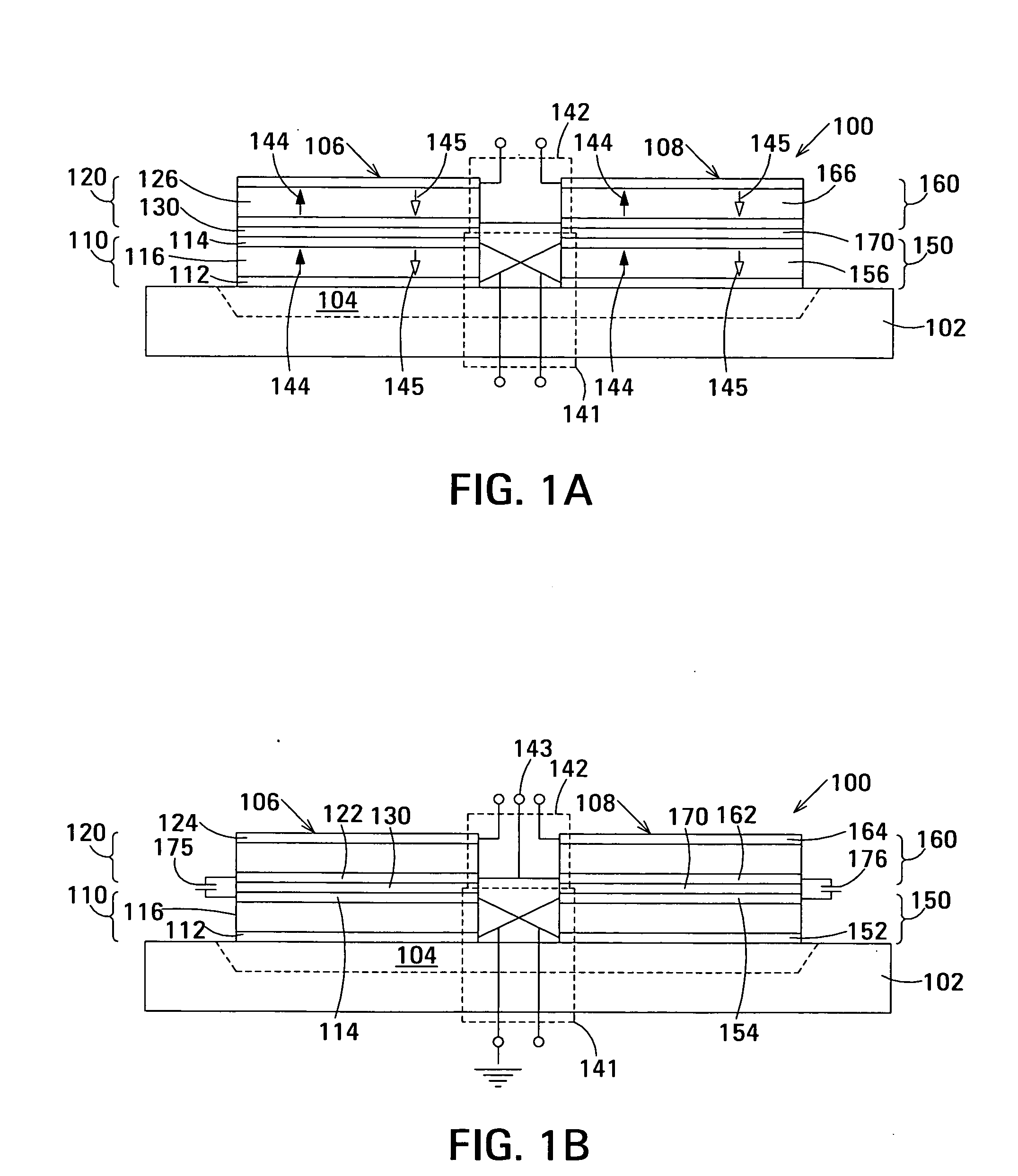
[0035] In the embodiments of the thin-film acoustically-coupled transformer described in above-mentioned U.S. patent application Ser. No. 10 / 699,481, such as the embodiment 100 shown in FIG. 1A, the respective piezoelectric layers 116, 126, 156 and 166 of FBARs 110, 120, 150 and 160 constituting transformer 100 are layers of normal c-axis material. The direction of the c-axis of normal c-axis material is indicated by an arrow 144. Alternatively, the respective piezoelectric layers 116 and 156 of lower FBARs110 and 150 are layers of normal c-axis material and the respective piezoelectric layers 126 and 166 of upper FBARs 120 and 160 are layers of reverse c-axis material. The direction of the c-axis of reverse c-axis material is indicated by an arrow 145. In a further alternative, the respective piezoelectric layers 116 and 156 of lower FBARs 110 and 150 are layers of reverse c-axis material and the respective piezoelectric layers 126 and 166 of upper FBARs 120 and 160 are layers of n...

exemplary embodiment 200

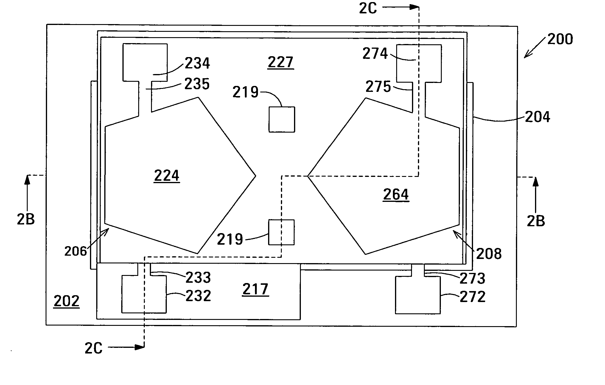
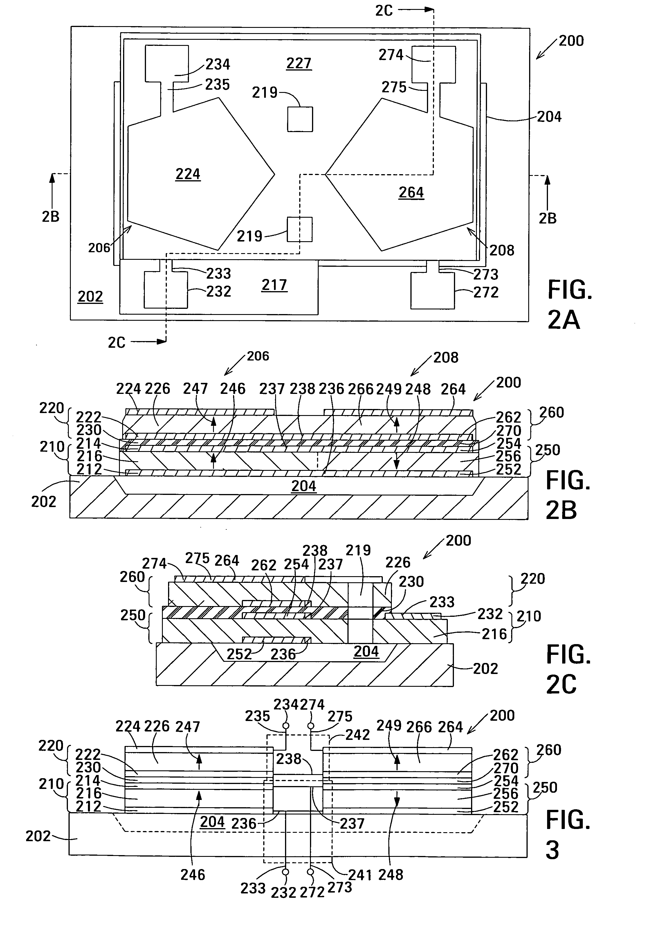
[0038]FIGS. 2A-2C show a plan view and two cross-sectional views, respectively, of an exemplary embodiment 200 of a thin-film acoustically-coupled transformer in accordance with the invention. Acoustically-coupled transformer 200 is capable of linking single-ended circuitry with balanced circuitry or vice versa, and has better common mode rejection than transformer 100 shown in FIG. 1A. The example shown additionally provides electrical isolation between primary and secondary. Acoustically-coupled transformer 200 has an impedance transformation ratio of 1:4 or 4:1 depending which of the electrical circuits is connected to the primary terminals of the transformer. Acoustically-coupled transformer 200 has a balanced secondary when connected as a 1:4 transformer or a balanced primary when connected as a 4:1 transformer.

[0039] Acoustically-coupled transformer 200 is composed of two stacked bulk acoustic resonators (SBARs) 206 and 208. Each SBAR is composed of a stacked pair of film bulk...

first embodiment

[0053] The embodiment of the acoustic decouplers 230 and 270 shown in FIGS. 2A-2C is a first embodiment in which acoustic decoupler 230 is composed of layer of acoustic decoupling material located between the electrode 214 of FBAR 210 and the electrode 222 of FBAR 220, and acoustic decoupler 270 is composed of layer of acoustic decoupling material located between the electrode 254 of FBARs 250 and the electrode 262 of FBAR 260.

[0054]FIG. 4A is an enlarged view showing in more detail part of SBAR 206 incorporating the above-mentioned first embodiment of acoustic decoupler 230. Referring additionally to FIGS. 2A and 2B, the corresponding part of SBAR 208 and acoustic decoupler 270 are similar in structure and will not be independently described. In the example shown, acoustic decoupler 230 is composed of a layer 231 of acoustic decoupling material located between the electrode 214 of FBAR 210 and electrode 222 of FBAR 220. Layer 231 of acoustic decoupling material additionally extends...


PUM

PropertyMeasurementUnit
insertion lossaaaaaaaaaa
center frequencyaaaaaaaaaa
thicknessaaaaaaaaaa

Abstract

An embodiment of the acoustically-coupled transformer has first and second stacked bulk acoustic resonators (SBARs) each having a stacked pair of film bulk acoustic resonators (FBARs) with an acoustic decoupler between the FBARs. Each FBAR has opposed planar electrodes with piezoelectric material between the electrodes. A first electrical circuit connects one FBARs of the first SBAR to one FBAR of the second SBAR, and a second electrical circuit connects the other FBAR of the first SBAR to the other FBAR of the second SBAR. The c-axis of the piezoelectric material of one of the FBARs is opposite in direction to the c-axes of the piezoelectric materials of the other three FBARs. This arrangement substantially reduces the amplitude of signal-frequency voltages across the acoustic decouplers and significantly improves the common mode rejection of the transformer. This arrangement also allows conductive acoustic decouplers to be used, increasing the available choice of acoustic decoupler materials.

Description

RELATED APPLICATIONS [0001] This application is a continuation-in-part of U.S. patent application Ser. No. 10 / 699,481 of Larson III et al. and is related to U.S. patent application Ser. No. 10 / XXX,XXX of Larson III et al. entitled Film Acoustically-Coupled Transformers with Two Reverse C-Axis Piezoelectric Elements (Agilent Docket No. 10040728) and filed on the filing date of this application, both of which applications are assigned to the assignee of this disclosure and are incorporated herein by reference.BACKGROUND [0002] Transformers are used in many types of electronic device to perform such functions as transforming impedances, linking single-ended circuitry with balanced circuitry or vice versa and providing electrical isolation. However, not all transformers have all of these properties. For example, an autotransformer does not provide electrical isolation. [0003] Transformers operating at audio and radio frequencies up to VHF are commonly built as coupled primary and second...

Claims


Application Information

Patent Timeline
Patent Type & Authority Applications(United States)
IPC IPC(8): H03H9/13H03H9/17H03H9/60
CPCH03H9/132H03H9/584Y10T29/42H03H9/605H03H9/587H01L2224/48091H01L2224/49175H01L2924/00014H03H9/60H03H9/0095
Inventor LARSON, JOHN D. IIIOSHMYANSKY, YURY
Owner AVAGO TECH INT SALES PTE LTD
Why Eureka
Try Eureka