Apparatus and methods for improving common mode rejection ratio

A technique for binary weighted, control logic circuits used in DC-coupled DC amplifiers, amplifiers with semiconductor devices/discharge tubes, electrical components, etc.

Active Publication Date: 2015-08-19
ANALOG DEVICES INT UNLTD
View PDF10 Cites 2 Cited by
  • Summary
  • Abstract
  • Description
  • Claims
  • Application Information

AI Technical Summary

Problems solved by technology

[0002] exist figure 1 The differential amplifier 106 shown in is only ideally amplifying the difference between

Method used


Image

  • Apparatus and methods for improving common mode rejection ratio
  • Apparatus and methods for improving common mode rejection ratio
  • Apparatus and methods for improving common mode rejection ratio

Examples


Embodiment Construction

[0013] The following detailed description of certain embodiments presents various descriptions of specific embodiments of the invention. However, the invention can be embodied in many different ways as defined and covered by the claims. In this specification, reference to like reference numerals in the drawings may indicate identical or functionally similar elements.

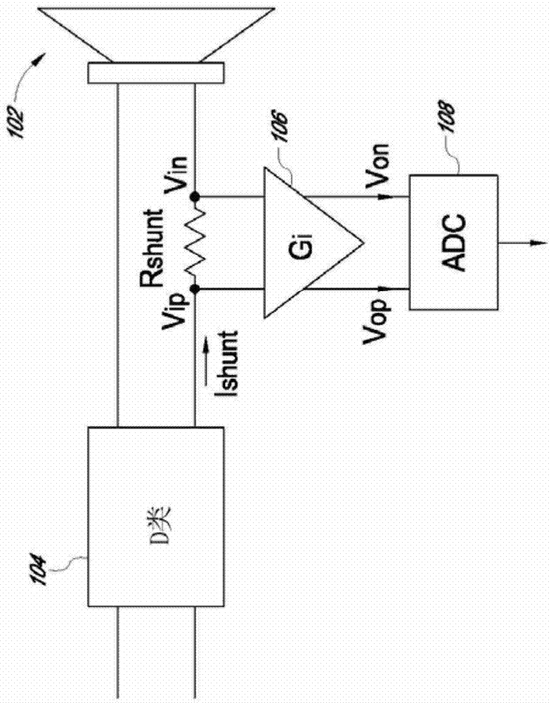
[0014] Having a relatively high common-mode rejection ratio is useful in many situations. For example, it is ideal for sensing current into a load. For example, figure 1 An arrangement of components that may be found in an electronic device is shown. A class D amplifier 104 is used to drive a transducer or speaker 102 . However, due to the output floating nature of the class D amplifier 104 and the switching output, observation of the output current is relatively difficult. For example, if the transducer / speaker 102 fails, the failure should be sensed to protect the class D amplifier 104 from damage.

[00...


PUM


Abstract

In certain applications, differential amplifiers with infinite common mode rejection ratios are desirable. However, resistance mismatches due to imperfections in the manufacturing create finite common mode rejection ratio in differential amplifiers degrading their performance. Disclosed are apparatus and method for improving the common mode rejection ratio of practical differential amplifiers.

Description

technical field [0001] The present invention relates generally to electronic devices and, more particularly, to improving the common mode rejection ratio of differential amplifiers. Background technique [0002] exist figure 1 The differential amplifier 106 shown in is only ideally amplifying the difference between the voltages Vip and Vin; however, practical differential amplifiers also amplify the common-mode input voltage. The common-mode rejection ratio (CMRR) of a differential amplifier is defined as a performance measure of the ratio of the differential gain of a differential amplifier to its common-mode gain. What is needed is a differential amplifier with improved CMRR. Contents of the invention [0003] One embodiment includes an apparatus, wherein the apparatus includes a first circuit configured to generate an offset based at least in part on a common-mode voltage as a differential signal input to a differential amplifier; and configured to scale the offset to...

Claims


Application Information

Patent Timeline
IPC IPC(8): H03F3/45
CPCH03F3/45479H03F2203/45112H03F2200/129H03F3/187H03F3/2173H03F3/45475H03F3/45932H03F3/45991H03F2203/45528
Inventor 倪金华李丹
Owner ANALOG DEVICES INT UNLTD
Why Eureka
Try Eureka