Planar transformer with reduced parasitic loss

A technology of planar transformers and transformers, applied in the direction of fixed transformers or mutual inductance, transformer/inductor components, transformer/inductor coils/windings/connections, etc., can solve problems such as impact

Pending Publication Date: 2022-05-27
墙盒充电器有限公司
View PDF0 Cites 0 Cited by
  • Summary
  • Abstract
  • Description
  • Claims
  • Application Information

AI Technical Summary

Problems solved by technology

[0006] Additionally, the primary and secondary windings of a transformer can adversely affect each other due to mutual parasitic capacitive coupling
[0007] Therefore, there is room for improvement regarding loss reduction techniques in the field of planar transformers

Method used


Image

  • Planar transformer with reduced parasitic loss
  • Planar transformer with reduced parasitic loss
  • Planar transformer with reduced parasitic loss

Examples


example

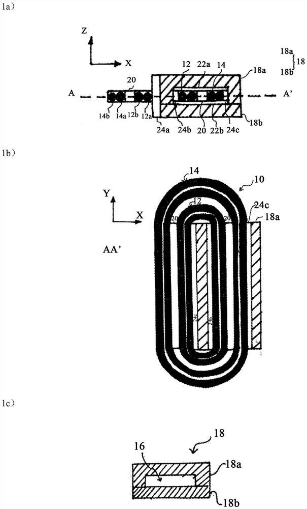
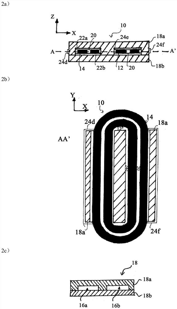
[0103] 1. A planar transformer, comprising:

[0104] Planar first primary coil;

[0105] a planar first secondary coil inductively coupled to the first primary coil; and

[0106] a transformer core for guiding magnetic flux generated by the first primary coil and / or the first secondary coil at least around a first opening of the transformer core;

[0107] The first primary coil and the first secondary coil are wound around the transformer core through the first opening.

[0108] 2. The planar transformer of example 1, wherein the first primary coil is disposed above the first secondary coil such that the first primary coil and the first secondary coil are perpendicular to the first secondary coil. The plane of a primary coil is spaced apart from each other in a direction perpendicular to the plane of the first secondary coil.

[0109] 3. The planar transformer of any preceding example, wherein the first primary coil and the first secondary coil are spaced apart in an axial ...


PUM

PropertyMeasurementUnit
thicknessaaaaaaaaaa
thicknessaaaaaaaaaa
inductanceaaaaaaaaaa

Abstract

The invention relates to a planar transformer (10) comprising a planar first primary coil (12), a planar first secondary coil (14) and a transformer core (18); the planar first secondary coil (14) is inductively coupled to the first primary coil (12), and the transformer core (18) is used for guiding magnetic flux generated by the first primary coil (12) and/or the first secondary coil (14) at least around a first opening (16) of the transformer core (18). The first primary coil (12) and the first secondary coil (14) are wound around the transformer core (18) through the first opening (16). The first primary coil (12) and the first secondary coil (14) are arranged on a first plane. The invention also relates to a battery charger comprising such a planar transformer.

Description

technical field [0001] The present invention belongs to the field of planar transformers, and particularly relates to a planar transformer with reduced parasitic capacitance, wherein the parasitic capacitance is coupled between a primary coil and a secondary coil of the planar transformer. Background technique [0002] Planar transformers are a subclass of transformers that are characterized by a special planar configuration. For electronic devices that require transformer functionality, planar transformers are widely used as a size reduction solution. The turns of the primary and secondary coils of the transformer are usually formed as thin copper sheets or etched on the PCB. [0003] The planar transformers known from the prior art suffer from a number of well-known disadvantages when used for AC currents in the high frequency range (eg at frequencies above 100 kHz). Some of the more related disadvantages are the so-called "skin effect" and the so-called "proximity effec...

Claims


Application Information

Patent Timeline
Patent Type & Authority Applications(China)
IPC IPC(8): H01F27/30H01F17/00
CPCH01F27/306H01F27/30H01F17/00H01F2027/2814H01F2027/2819H01F19/04H01F2019/085H02J7/02H01F27/2823H01F27/341H01F27/24H01F27/29
Inventor I·乌鲁蒂科埃切亚·德米格尔J·M·费尔南德斯·莫拉
Owner 墙盒充电器有限公司
Why Eureka
Try Eureka