Frame assembly for a license plate

a license plate and frame technology, applied in the field of license plate frame assembly, can solve the problems of difficult to receive a clear signal from the camera in covered areas or at night, the rear view mirror does not allow the operator, and the rear blind spot is particularly problemati

Inactive Publication Date: 2005-05-05
DECOMA INT
View PDF17 Cites 153 Cited by
  • Summary
  • Abstract
  • Description
  • Claims
  • Application Information

AI Technical Summary

Benefits of technology

[0004] The disadvantages of the prior art may be overcome by providing a license plate holder fitted with a camera and rearward lighting. According to one aspect of the invention, there is provided a license plate holder mountable at the rear of a motor vehicle. The holder has a frame assembly that includes a housing. A camera is mounted within the housing and produces a rearward image. A light is fixedly secured to the housing for rearward illumination. The light assists the camera in producing the rearward image during low lighting conditions.

Problems solved by technology

The rear view mirror does not, however, allow the operator to view a space immediately behind the rear of the motor vehicle.
The rear blind spot is especially problematic in sport utility vehicles and minivans.
It is, however, difficult to receive a clear signal from the camera in covered areas or at night.
These added systems detract from the aesthetics of the motor vehicle and require additional fasteners to attach to the vehicle.

Method used


Image

  • Frame assembly for a license plate
  • Frame assembly for a license plate
  • Frame assembly for a license plate

Examples


Embodiment Construction

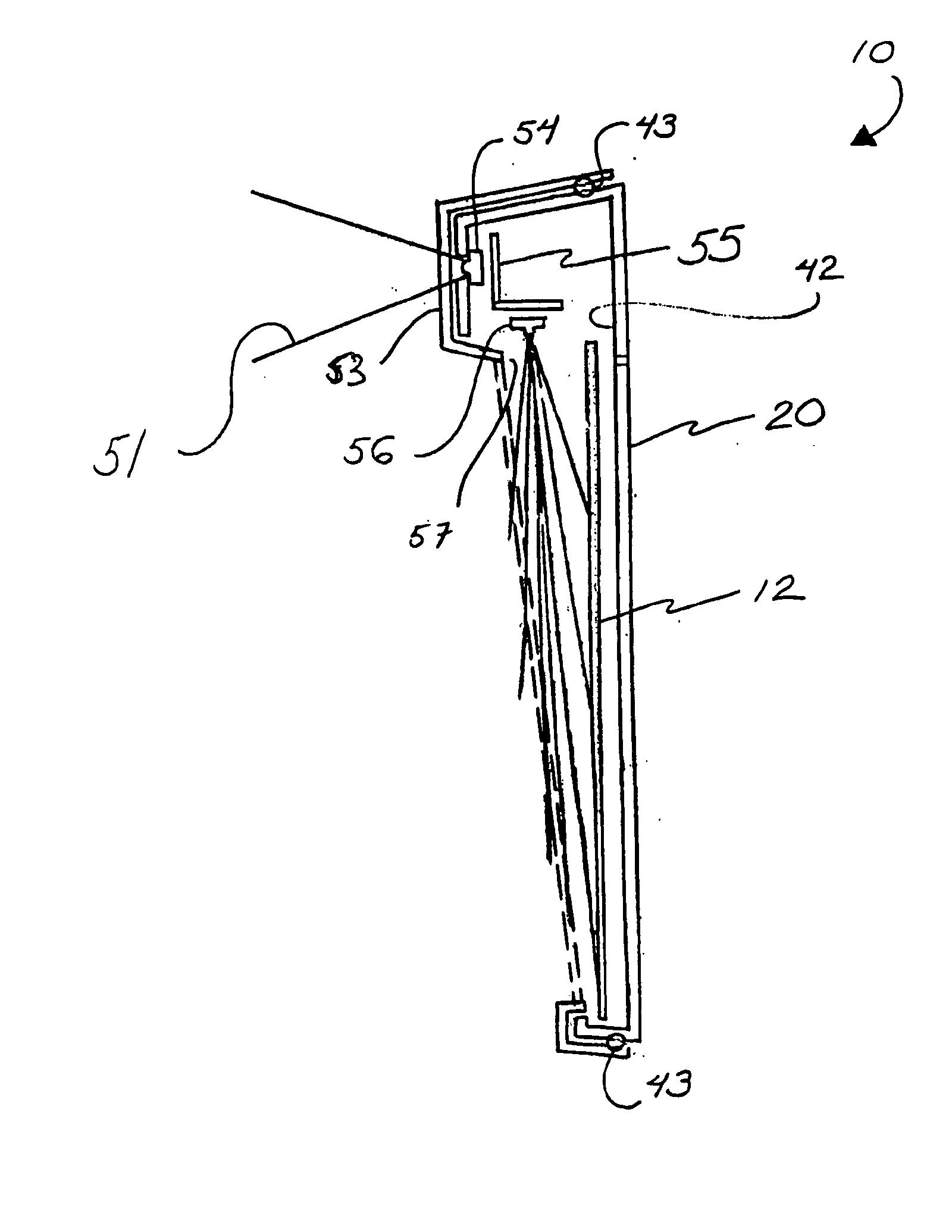
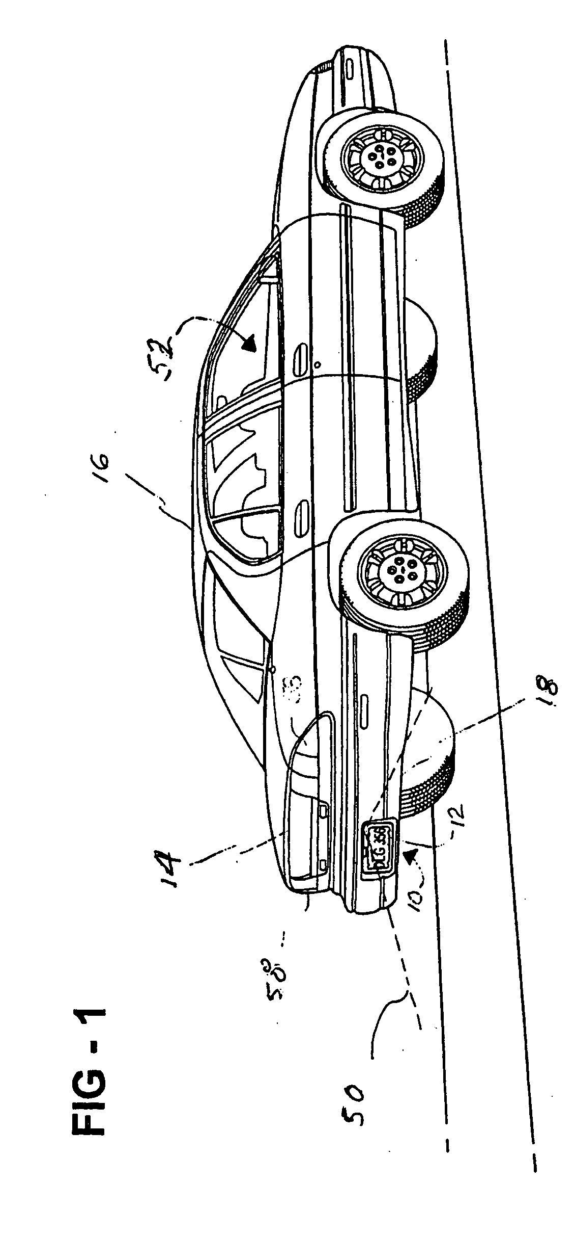
[0011] Referring to FIG. 1, a license plate holder, generally shown at 10, for mounting a license plate 12 on the rear end 14 of a motor vehicle 16. More specifically, the license plate holder 10 is disposed preferably on a rear bumper 18 of the motor vehicle 16. It is, however, appreciated that the license plate holder 10 may be mounted at various places along the back end 14 of the motor vehicle 16 including, but not limited to, a rear fascia, a decklid, and a tailgate.

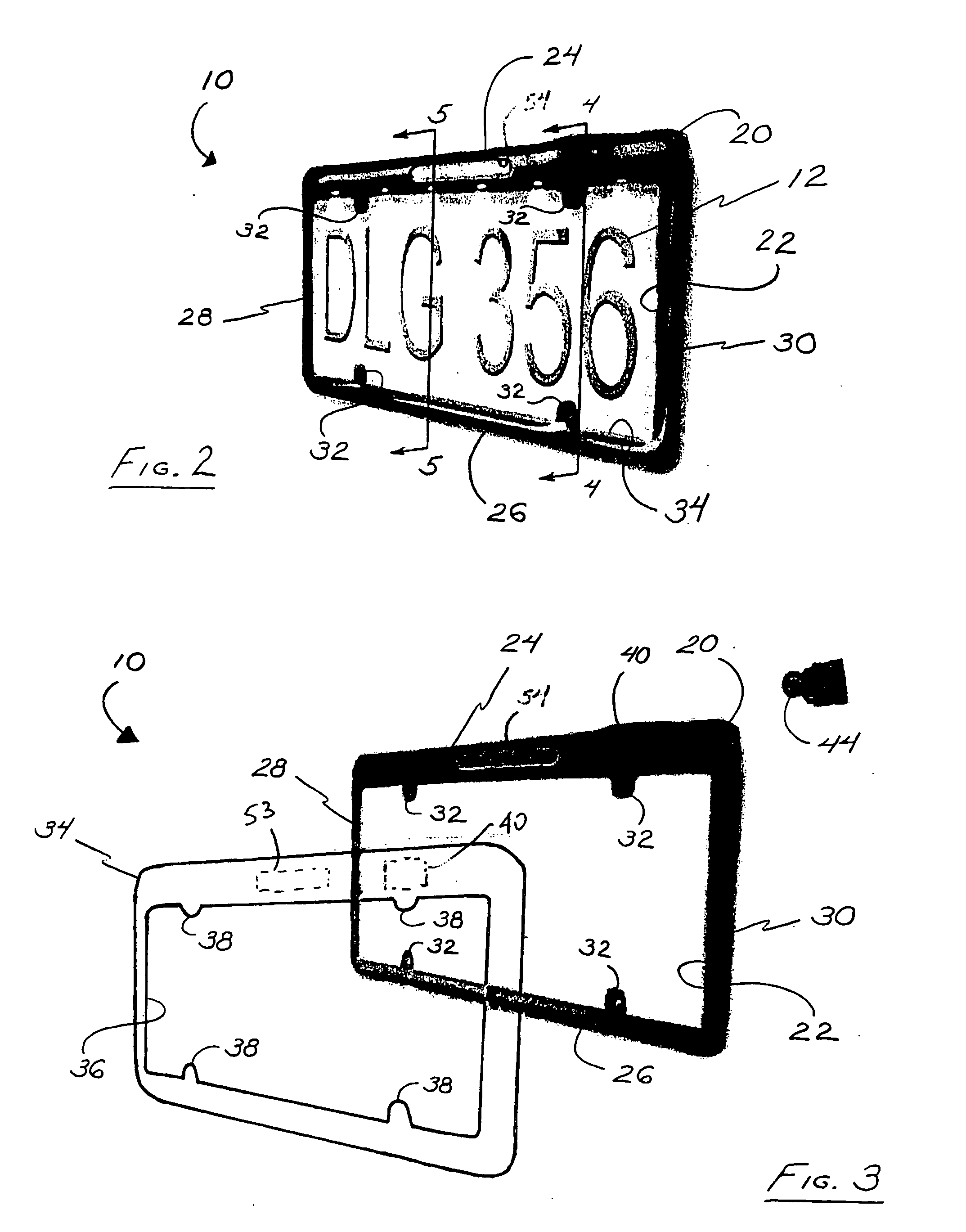
[0012] Referring to FIGS. 2 and 3, the license plate holder 10 includes a generally rectangular base frame 20 having an opening or window 22. The license plate 12 is retained within the opening 22 such that license plate numbers and letters are visible from behind the motor vehicle 16, as required by law.

[0013] The base frame 20 includes an upper segment 24, a lower segment 26, and sides 28, 30 extending therebetween. The upper 24 and lower 26 segments and the sides 28, 30 define the opening 22. The upper segment ...


PUM


Abstract

A frame assembly positions a license plate along a back end of a motor vehicle. The frame assembly includes a base frame adapted to be secured along the back end of the motor vehicle to retain the license plate thereto. A camera is secured to the base frame to produce an image representing an area adjacent to and behind the back end of the motor vehicle. A camera light is fixedly secured to the base frame for illuminating the area adjacent to and behind the back end of the motor vehicle. The camera light assists the camera in producing the image during low lighting conditions.

Description

FIELD OF THE INVENTION [0001] This invention relates to a frame assembly for a license plate. More particularly, the invention relates to a frame assembly for a license plate that incorporates a camera and a lighting mechanism to assist camera operation in low lighting conditions. DESCRIPTION OF RELATED ART [0002] A motor vehicle operator utilizes a rear view mirror to see an area behind the motor vehicle. The rear view mirror does not, however, allow the operator to view a space immediately behind the rear of the motor vehicle. This space is typically referred to as a rear blind spot. The rear blind spot is especially problematic in sport utility vehicles and minivans. [0003] To address this problem, various rear vision systems have been developed that provide the motor vehicle operator with a complete view of the space behind the motor vehicle. Typically, such a rear vision system includes at least one rearwardly facing camera mounted on the motor vehicle. The camera transmits an ...

Claims


Application Information

Patent Timeline
Patent Type & Authority Applications(United States)
IPC IPC(8): B60Q1/00B60Q1/22B60Q1/56B60R13/10F21V33/00
CPCB60Q1/0023B60Q1/56B60Q1/22
Inventor CUNNIEN, COLE J.
Owner DECOMA INT
Why Eureka
Try Eureka