System for providing pathway indications through unlit areas

Inactive Publication Date: 2005-05-05
HARWOOD RONALD P
View PDF13 Cites 10 Cited by
  • Summary
  • Abstract
  • Description
  • Claims
  • Application Information

AI Technical Summary

Benefits of technology

[0010] While these systems are suitable for their intended purposes, they are not ideally designed for applications such as described above. This is because the present invention provides improved energy efficiency over the systems known in the art, and is thus more economical. Additionally, the present invention is opti

Problems solved by technology

While these systems are suitable for their intended purposes, they

Method used


Image

  • System for providing pathway indications through unlit areas
  • System for providing pathway indications through unlit areas
  • System for providing pathway indications through unlit areas

Examples


Example

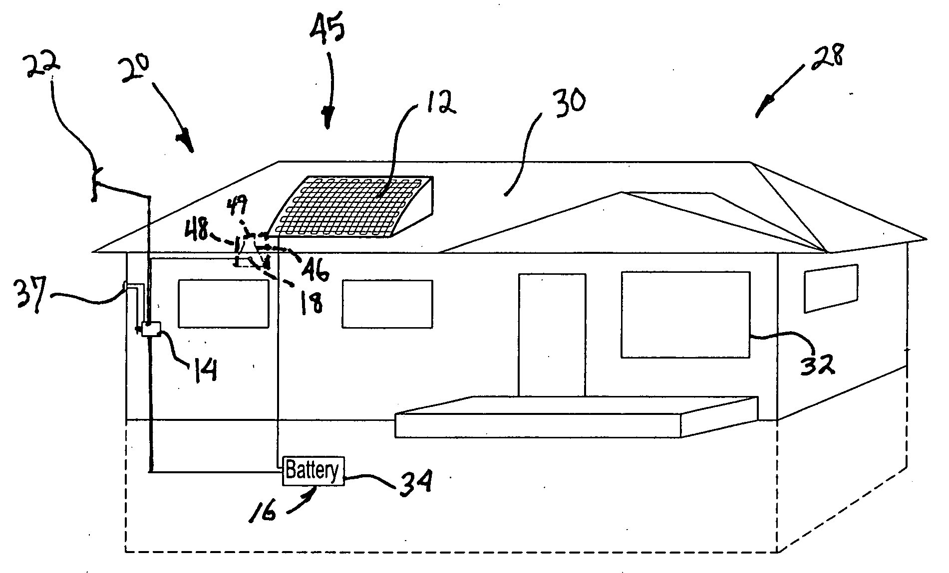
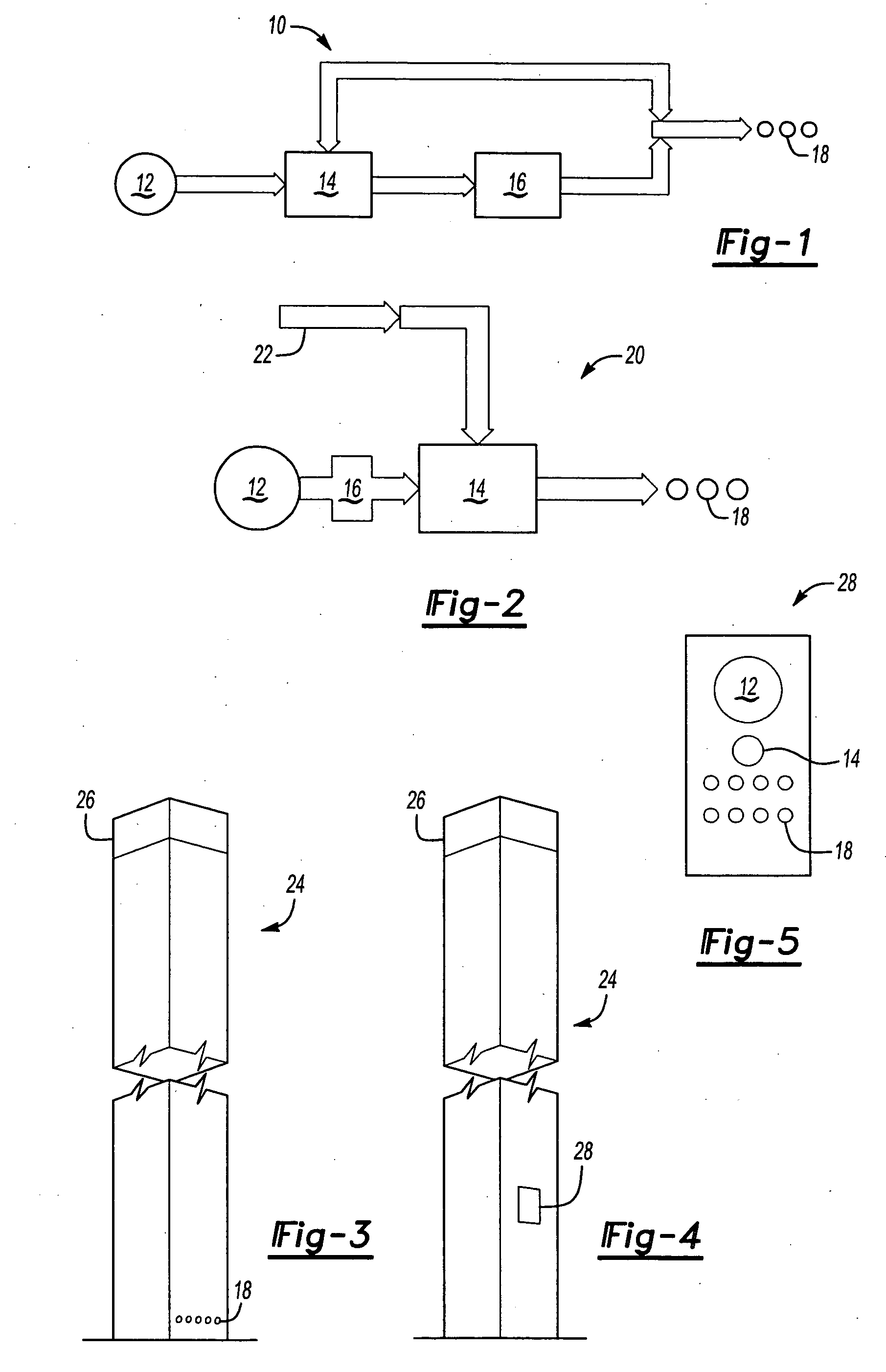
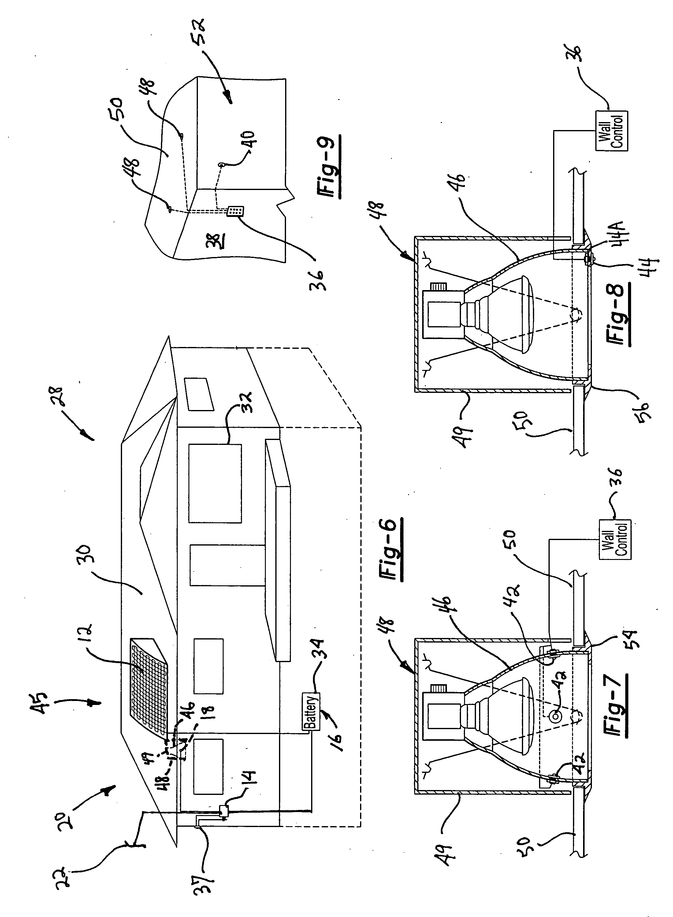
[0023]FIG. 1 illustrates an auxiliary lighting system 10 according to the present invention. The auxiliary lighting system 10 includes a photoelectric collector 12 positioned in such a manner as to receive a maximal amount of sunlight. If the auxiliary lighting system is to be used indoors, the collector could be placed indoors, in a place where it will be exposed to light, or it can be placed outdoors. The photoelectric collector 12 is then connected to an auto-switching energy sensor 14. The sensor 14 is then connected to one or more electrical storage devices 16. The storage devices 16 can then be connected to one or more LEDs 18 as the light source of the auxiliary lighting system 10. The sensor 14 can also provide an additional electric pathway directly from the photoelectric collector 12 to the LEDs 18.

[0024]FIG. 2 illustrates a modification of the present invention, shown as the auxiliary lighting system 20. In this embodiment, the photoelectric collector 12 is connected to ...


PUM


Abstract

An auxiliary lighting system contains at least one photoelectric cell to convert ambient light into energy and at least one light emitting diode. The photoelectric cell converts ambient light into energy which is stored in a storage cell. A switching system provides energy from the storage cell to the light emitting diode upon certain conditions, generally by time or by lack of ambient light.

Description

BACKGROUND OF THE INVENTION [0001] The present application is a continuation-in-part of application Ser. No. 10 / 202,746, filed Jul. 25, 2002, which is incorporated herein in its entirety. Application Ser. No. 10 / 202,746 is currently pending as of the filing date of this application. The benefit of said application Ser. No. 10 / 202,746 is claimed under 35 U.S.C. §120. [0002] U.S. patent application Ser. No. 10 / 202,746 claimed to the benefit, under 35 U.S.C. §119(e), of the provisional application filed Jul. 26, 2001 under 35 U.S.C. §111(b), which was granted Ser. No. 60 / 307,947. The provisional application 60 / 307,947 is hereby incorporated by reference. [0003] I. Field of the Invention [0004] The present invention relates to an improved system for providing pathway indication through unlit areas. For example, outdoor parking lots are often illuminated by light poles, which for economic reasons, are often designed to be automatically turned off after a set time, for example at midnight...

Claims


Application Information

Patent Timeline
IPC IPC(8): F21S8/00F21S9/03F21V23/04
CPCF21S8/02F21S9/032F21Y2101/02F21W2111/023F21W2131/10F21V23/0442F21Y2115/10Y02B20/72
Inventor HARWOOD, RONALD P.
Owner HARWOOD RONALD P
Why Eureka
Try Eureka