

Power supply device comprising several switched-mode power supply units that are connected in parallel
- Summary
- Abstract
- Description
- Claims
- Application Information
AI Technical Summary
Benefits of technology
Problems solved by technology
Method used
Image

Examples
Embodiment Construction
Cross Reference to Related Applications
[0001] This application is a National Stage of International Application No. PCT / EP03 / 03275, filed March 28, 2003, which claims priority to German patent application 102 14 190.8, the entire contents of each of which are hereby incorporated by reference.
Field of the Invention
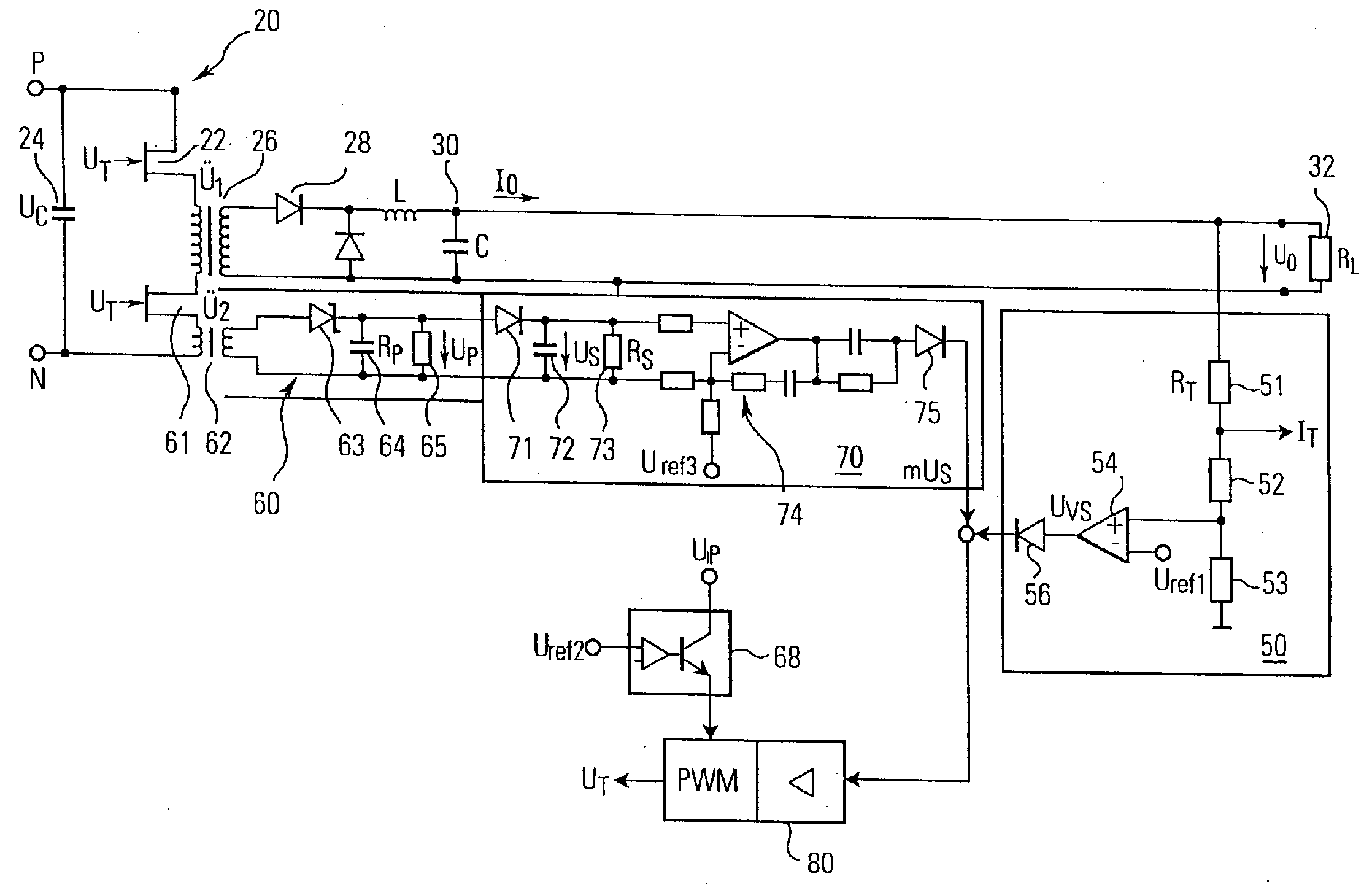
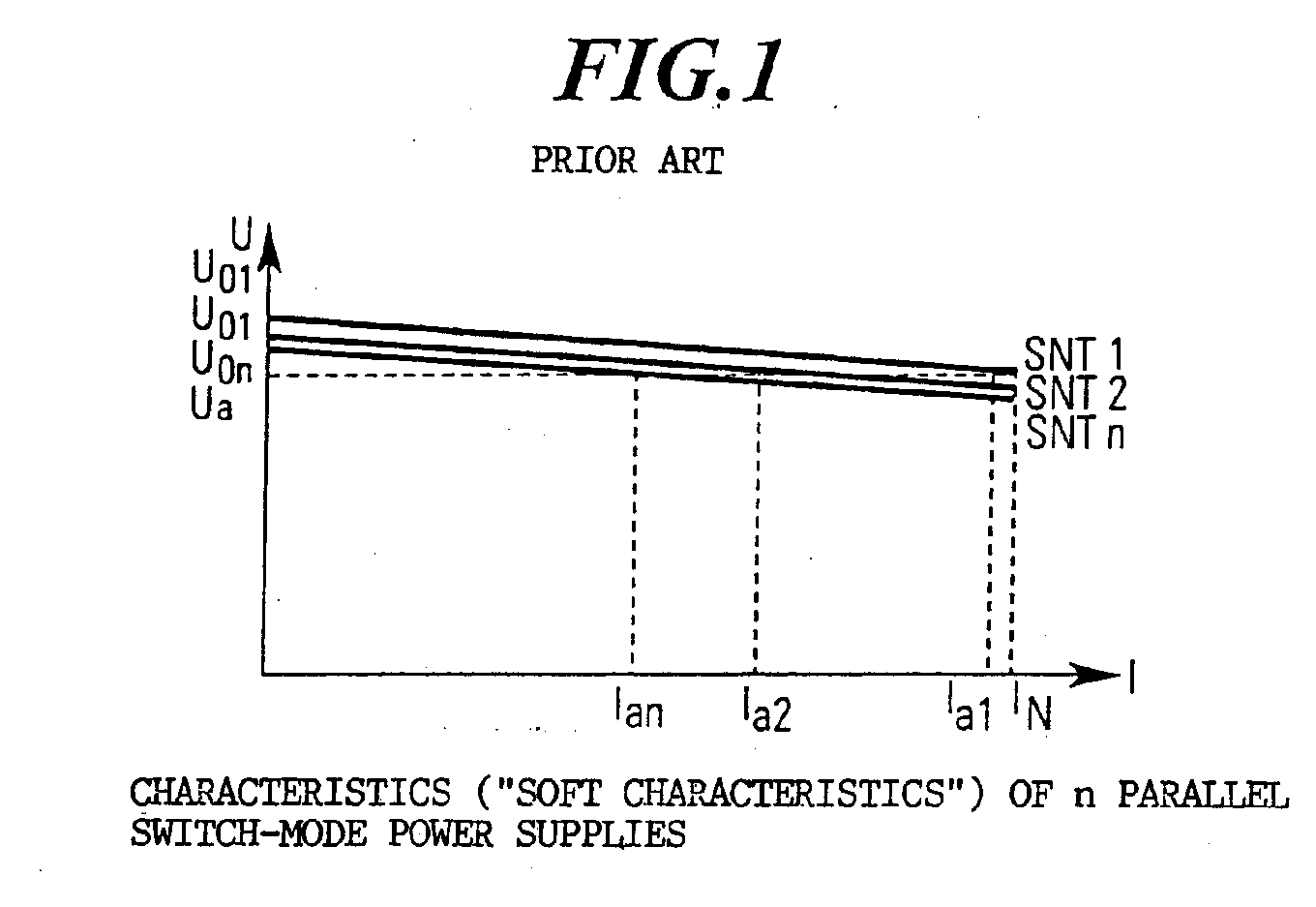
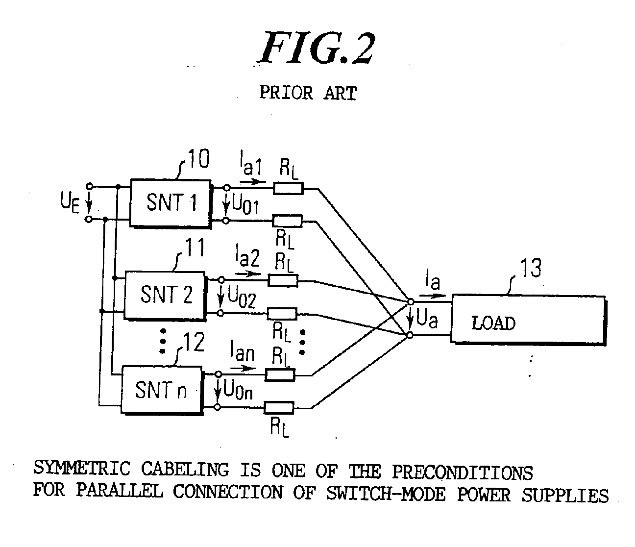
[0002] The invention relates to a power supply device having several switch-mode power supplies connected in parallel to supply at least one load, each switch-mode power supply generating an output current and an output voltage, and having a control device for each switch-mode power supply. The control device controls the output voltage of the switch-mode power supply which is a dependent on the output current and a load resistance.
Background of the Invention
[0003] The basic principles of switch-mode power supplies connected in parallel are described, for example, in Elektronik, Volume 13, 2000, pages 114-118 "Schaltnetzteile parallel geschaltet – technische Details zur pas...
PUM
 Abstract
Description
Claims
Application Information